 |
|||
|
|
|||
|
|
|||
| ||||||||||
|
|
 TM 9-2910-226-34
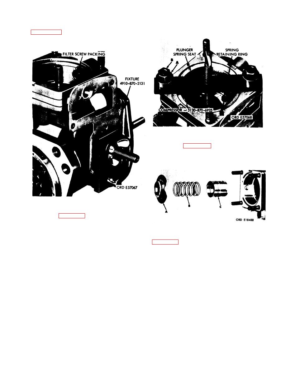
3-14. Removal of Tappet Assembly. a. Refer to
packing. Remove fixture.
Figure 3-23. Removing spring retaining ring using spring
compressor--5120-870-6925.
seat (A), plunger outer spring (B), and tappet
assembly (C).
Figure 3-22. Removing fixture 4910-870-2131 prior to removal
of tappet assembly.
so that holes in spring retaining ring (C) are ac-
cessible. Install two stud sleeves (A) and hydraulic
head nuts (B). Turn thumb screw clockwise finger
Figure 3-24. Removing tappet assembly.
tight to compress plunger outer spring. Remove
3-15. Removal of Quill Shaft Assembly. a. Refer to
spring retaining ring (C) using suitable pliers.
Release tension on plunger outer spring by turning
two capscrews (B), copper gaskets (C), and quill
thumb screw counterclockwise and remove spring
shaft pad cover (D). Discard copper gaskets.
compressor from housing.
Remove and discard cover gasket (E).
3-9
|
|
Privacy Statement - Press Release - Copyright Information. - Contact Us |
