 |
|||
|
|
|||
|
Page Title:
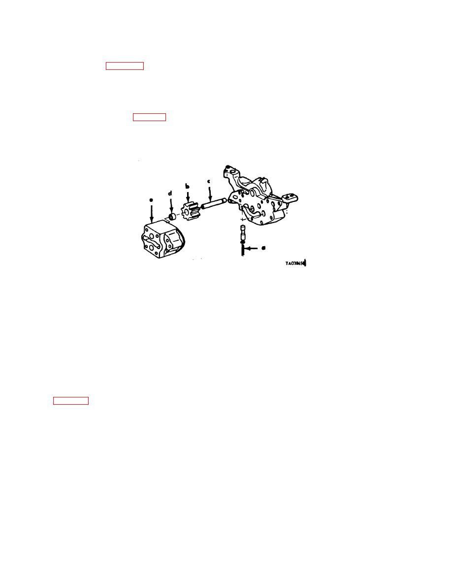
Figure 3-109. Oil pressure regulator and oil pump-points of measurement. |
|
||
| ||||||||||
|
|
 C2, TM 9-2815-213-34
Fig.
Ref.
Point of Measurement
New Dimensions Wear Limits
No.
Letter
(inches)
(inches)
c. Camshaft Gear (para 3-32).
3-108.
f
Inside diameter of gear ............................................................ 1.7980 to 1.7985
*
g
Outside diameter of shaft ......................................................... 1.7985 to 1.7990
g
Gear to shaft clearance............................................................ PRESS FIT
h
Camshaft to crankshaft backlash ............................................. 0.006 to 0.009
0.009
j
Camshaft and clearance .......................................................... 0.007 to 0 001
0.011
d. Air Compressor Drive Gear (para 3-9),
3-108.
k
Inside diameter of gear ............................................................ 12885 to 1.2890
*
I
Outside diameter of shaft ......................................................... 12890 to 12895
Gear to shaft clearance............................................................ PRESS FIT
m Gear to camshaft gear backlash .............................................. 0.006 to 0.009
0.009
Figure 3-109. Oil pressure regulator and oil pump-points of measurement.
a Valve Spring Measurements.
3-109.
a
Free spring length (approx.)...........................................................
3.410
*
a
Compressed length (at valve opening) (Force 45 Ibs.) ..................
2.125
a
Compressed length (at max. valve opening) (Force of 35 Ibs.) ....
71.438
b. Oil Pump
3-109
b
Pump gear(s) outside diameter......................................................
2.399 to 2.400
2397
c
Shifts (3) outside diameter .............................................................
0.8745 to 0.8750
0.8740
d
Bushings (4) inside diameter .........................................................
0.8770 to 0.8775
0.8785
e
Gear pockets (2) inside diameter...................................................
2.4070 to 2.4090
2.4105
Gear pockets (2) inside depth ........................................................
12490 to 12510
1.252
3-183. cylinder Head
a. Valves, Guides and Valve Seats.
3-110.
a
Outside diameter of valve stem ..................................................
0.4500 to 0.4512
0.4490
b
Inside diameter of valve guide ....................................................
0.4525 to 0.4532
0.4545
c
Valve guide protrusion ................................................................
695 to 0.710
*
d
Intake valve seat insert thickness ...............................................
02580 to 0.2200
*
e
Exhaust valve seat insert thickness ............................................
0.02180 to 0.820
*
3-110.
f
Swirl plate thickness (intake) ......................................................
0.0200 to 0.0210
*
c
Head counterbore inside diameter 0 (std) ..................................
1.995 to 2.0005
*
ad/ae Angle of seating face-valve and insert seat ................................
30 Degrees
*
c
Valve seat width..........................................................................
0.1250
g
Valve springs.(5340-082-0126) ..................................................
0.0780
Free length..................................................................................
2.090
Load Length: Valve open-1.317 ..................................................
161 to 179 Ibs.
155 Ibs.
Number of coils ...........................................................................
6'/..
3-68
|
|
Privacy Statement - Press Release - Copyright Information. - Contact Us |
