 |
|||
|
|
|||
|
Page Title:
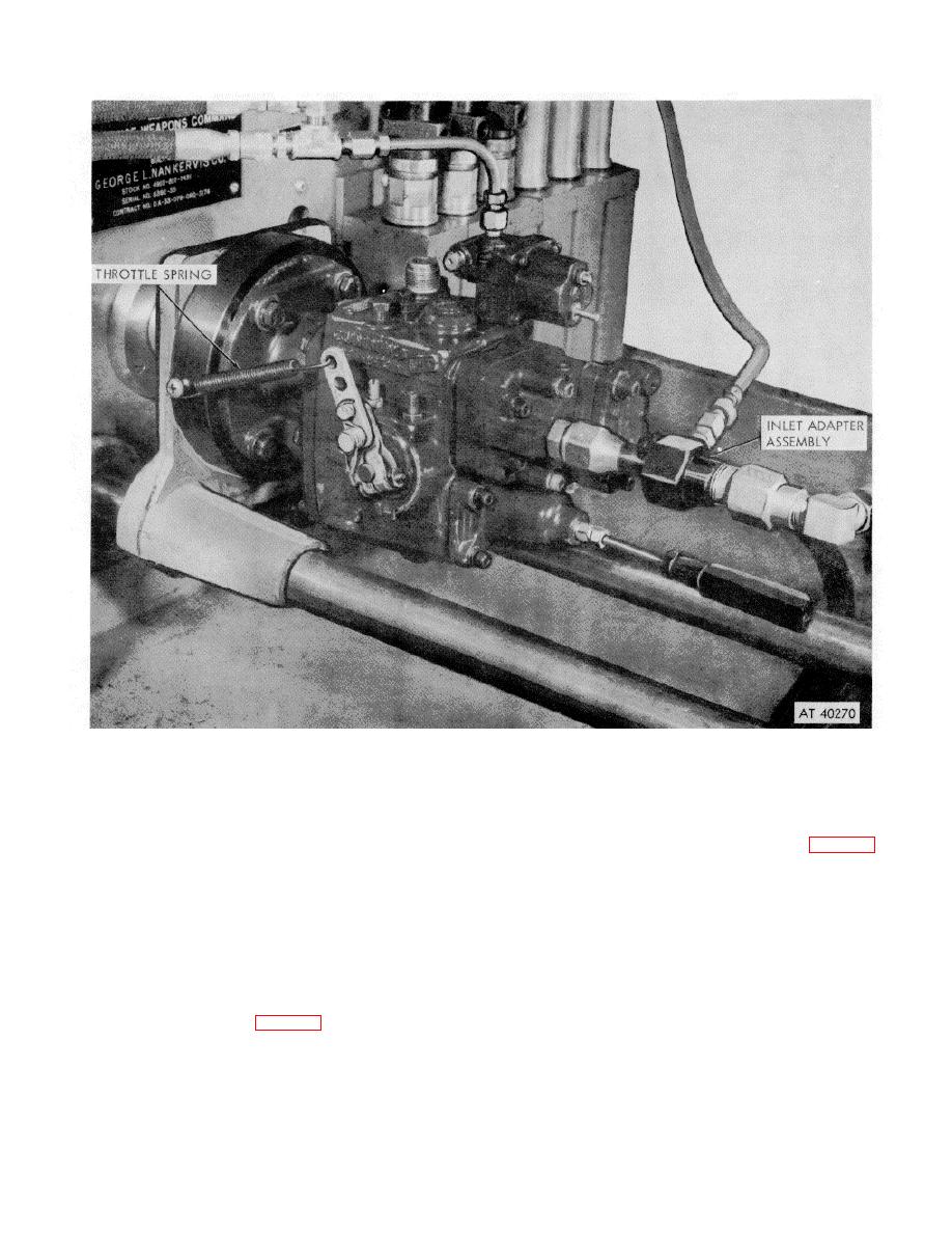
Figure 3-82. Pump to stand drive shaft engagement. |
|
||
| ||||||||||
|
|
 *TM 9-2815-213-34
Figure 3-82. Pump to stand drive shaft engagement.
Blue represents size 1 (oversize). Standard size
can be used. Minimum 0.001 inch interference fit is
diameter is 0.37460-0.37468 and oversize diameter is
required.
0.37470-0.37478.
(4) To locate a new governor barrel in the housing,
(2) If governor barrel is worn too large for the
scribe a center line on barrel and housing, lining up the
oversize plunger, replace barrel by heating housing in
fuel passages to prevent fuel flow restriction (fig. 3-85).
boiling water 112 to 2 minutes, and press out worn
(5) Heat housing in oven to 300 degrees Fahrenheit.
governor barrel.
(6) Cool barrel in dry ice or by another suitable
method.
CAUTION
(7) Coat new governor barrel with high pressure
Remove spring dowel which secures barrel in
lubricant.
fuel pump, before attempting to remove
(8) Place governor barrel in housing bore lining up
governor barrel. To pull spring dowel, insert
scribe marks, then press barrel into housing with arbor
wire hook into hole provided in dowel and
press.
remove.
(9) Select new governor plunger and fit it in barrel. If
(3) Check barrel bore in housing to determine
plunger enters try larger size plunger. If the larger size
whether standard size barrel (fig. B-17)
plunger fits loosely in bore, replace barrel and plunger.
3-45
|
|
Privacy Statement - Press Release - Copyright Information. - Contact Us |