 |
|||
|
|
|||
|
Page Title:
Assembly of Sub-Assemblies and pump |
|
||
| ||||||||||
|
|
 *TM 9-2815-213-34
governor plunger. Assembled in reverse order of
(3) Apply thin coat of high pressure lubri-
(para. 3-102.b. (2)).
cant and press bushing flush into housing bore
(5) Insure clearance between thrust washer
using arbor press.
and drive plunger governor as shown in figure
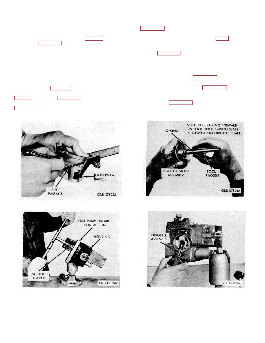
(4) Attach fuel pump fixture (42, fig. B-28)
3-89.
as shown in figure 3-86.
(6) Install governor plunger assembly as
(5) Line ream bushing to 0.7495/0.7505
shown in figure 3-78.
inch.
(7) Install new filter assembly. Assemble in
3-106. Assembly of Sub-Assemblies and
reverse order of disassembly (para. 3102,
pump
b. (1)).
a. Pump Housing.
b. Tachometer Drive Assembly. Assemble in re.
(1) Install all pipe plugs, dowels, and clips
verse order of disassembly (para. 3-102.a. (7)).
using new O-Rings as required.
c. Governor Spring Pack Assembly. Assemble
(2) Assemble throttle assembly in reverse
in reverse order of disassembly (para. 3-102.a.
order of disassembly (para. 3-102.b. (3)), in-
(6)).
stalling new 0 Ring with O-Ring assembly tool (37,
d. Fuel Pump Gear. Assemble in reverse order
of disassembly (para. 3-102.a. (5)) insuring that
(3) Install throttle assembly as shown in
notches in housing and cover correspond.
e. Mainshaft Cover and Governor Assembly.
(4) Install compression spring and assemble
Figure 3-87. Throttle shaft O-ring installation.
Figure 3-85. Scribing governor barrel.
Figure 3-86. Reaming mainshaft bushing.
Figure 3-88. Throttle assembly installation.
3-47
|
|
Privacy Statement - Press Release - Copyright Information. - Contact Us |
