 |
|||
|
|
|||
|
Page Title:
Figure 3-11. Ring groove wear check. |
|
||
| ||||||||||
|
|
 *TM 9-2815-213-34
(5) Check bolt pad corner radius (0.25 0.2700
inch). If radius does not check to tolerance, machine to
proper dimensions.
k. Inspect connecting rod bearing caps using ball
point micrometer, dial indicator thickness gage, or
Comparator. Refer to paragraph 3-177, for shell
thickness and allowable wear.
l. Inspect pistons for scoring,
burning,
or
damaged ring grooves and cracks inside piston struts. A
badly scored piston must be replaced; a slightly scored
piston may be cleaned and reused.
m. Inspect top of piston for burned spots indications
of over-heating such as carbon formation on underside
of the piston. Replace burned pistons.
n. Using ring groove wear gage (52, fig. 28) check
groove wear as follows: (fig. 3-11)
(1) Insert ring groove wear gage (52, fig. B-
28) into each of the top and second ring grooves.
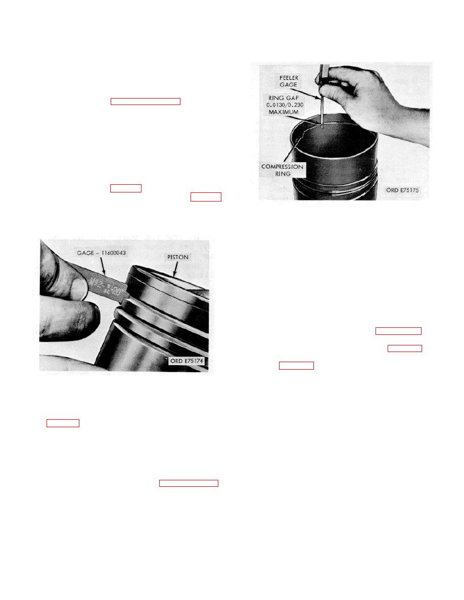
Figure 3-12. Piston ring gap check.
(2) If shoulders of gage touch ring grooves
lands, piston must be discarded.
NOTE
Measurement should be
taken at
ambient air temperature
of 70/90
degrees Fahrenheit.
q. Using inside micrometer, measure piston pin
bore; discard piston if bore exceeds 2.005-inch.
3-16. Repair
Repair of the connecting rod and piston assembly is
limited to general procedures as outlined in paragraph 2-
7. Any defect, or measurement outside the tolerances
listed in repair and rebuild standards (paras. 3-177, and
3-178) is cause for replacement. If piston pin bushings
must be replaced use bushing driver (46, fig. B-28) for
bushing removal and replacement. Check with plug
gage (50, fig. B-28).
3-17. Assembly
Figure 3-11. Ring groove wear check.
Assemble rod to piston in reverse order of paragraph 3-
13.
o. Check ring gap as follows:
NOTE
(1) Insert each compression ring into worn
portion of cylinder liner, seating it squarely using a piston
When installing rings insure the word
head (fig. 3-12).
"Top" inscribed on the ring, is to the top
(2) Measure ring gap with feeler gage. The
of the piston.
allowable ring gap is 0.013/0.0230: Rings exceeding this
limit should be discarded.
3-18. Installation
(3) If necessary, file ring ends to obtain gap of
a. Lubricate rod and piston assembly with OE- 10
0.0130/0.0230 inch.
lubricant.
p. Measure piston skirt diameter with micrometer at
b. Compress piston rings with suitable cylindrical
right angle to piston pin bore. Refer to paragraph 3-178,
ring compressor.
for wear limits. If piston wear exceeds 0.004-inch
c. Remove connecting rod cap from bolts and
discard piston.
make certain bolt heads are seated squarely on rod
shoulder. These parts are not interchangeable (fig. 3-
26).
3-7
|
|
Privacy Statement - Press Release - Copyright Information. - Contact Us |
