 |
|||
|
|
|||
|
Page Title:
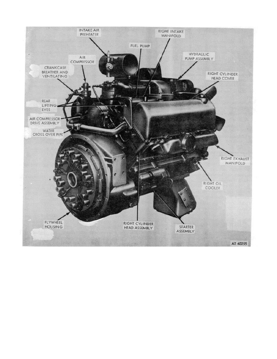
Figure 1-2. Model V8-300 engine assembly--3/4 right rear view. |
|
||
| ||||||||||
|
|
 *TM 9-2815-213-34
Figure 1-2. Model V8-300 engine assembly--3/4 right rear view.
ing supplies oil to no. 2 and 6 connecting rods.
cover up to the bushing in support cover.
(f) Oil flows through a crossover at front of
(3) Cooling System. The coolant is circulated by a
block to supply no. 1 cam bushing and no. 1 main
centrifugal type water pump mounted on the front of the
bearing. No. 1 main bearing supplies oil to no. 1 and no.
engine and is belt driven by the crankshaft pulley. The
5 connecting rods.
water circulates around the cylinder sleeves, through the
(g) The left bank rocker arms are oiled
cylinder heads, and around the injector sleeves. The
injectors are seated in copper injector sleeves for quick
intermittently through no. 1 cam bushing.
(h) Right bank tappets are oiled from drilling at
dissipation of heat. Outlet castings at the front of the
heads are connected to the thermostat housing. The
rear of engine.
thermostat maintains engine operating temperature
(i) Oil flows through a drilling in the air
between 173 degrees and 186
compressor gear case to the rear of the case, through a
drilling in the compressor support
1-3
|
|
Privacy Statement - Press Release - Copyright Information. - Contact Us |
