 |
|||
|
|
|||
|
Page Title:
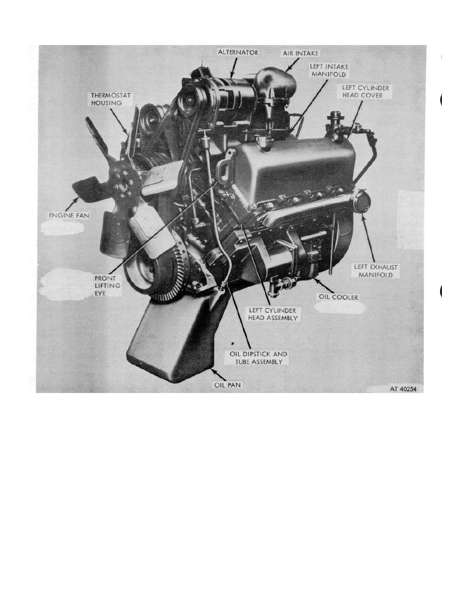
Figure 1-1. Model V8-300 engine assembly--3/4 left front view. |
|
||
| ||||||||||
|
|
 *TM 9-2815-213-34
Figure 1-1. Model V8-300 engine assembly--3/4 left front view.
pump. Oil is delivered to all working parts of the engine
(b) The oil flow crosses in front of block to left bank
through drillings in the block, cylinder head, crankshaft,
through oil filter and into cooler. From cooler, oil flows to
and rocker levers. Lubricating oil is forced through the
left bank oil drilling at rear of engine. The oil pump by-
crankshaft to lubricate the main and connecting rod
pass dumps oil directly into pan.
bearings. Lubricating oil pressure is controlled by a
(c) From left bank oil drilling, at rear of engine, oil
regulator which is an integral part of the oil pump
flows to no. 4 cam bushing and no. 4 main bearing which
assembly. The air compressor receives pressure
in turn supplies no. 3 and 7 connecting rods.
lubrication from the engine oil supply. The oil flow cycle
(d) Right bank rocker arms are oiled intermittently
is as follows.
through no. 5 cam bushing.
(a) Oil is drawn to oil pump through suction tube, in
(e) From left bank oil drilling, oil flows to left bank
oil pan. It is then pumped through a passage in rear of
tappets, to no. 2 and 3 cam bushings, and no. 2 and 3
block through right bank water header cover to front of
main bearings. No. 3 main bear-
the block.
1-2
|
|
Privacy Statement - Press Release - Copyright Information. - Contact Us |
