 |
|||
|
|
|||
|
|
|||
| ||||||||||
|
|
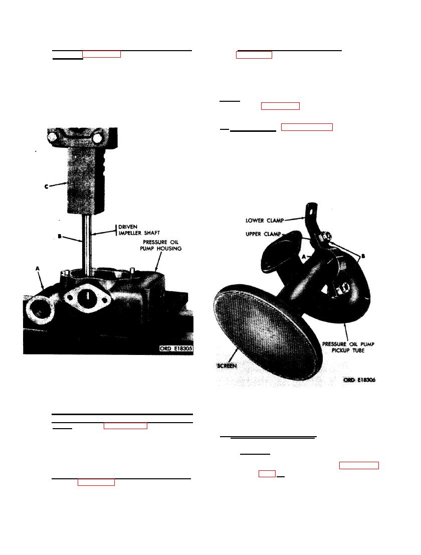 (3) Install pressure oil pump driven impel-
(6) Install oil pump drive gear. Refer to
ler shaft. Figure 377. (A) Position pres-
sure oil pump housing on press plates
quence of illustrations and instructions
a s shown.
(B) Start driven impeller
to install oil pump drive gear.
shaft straight into shaft bore in pressure
oil pump housing. (C) Press shaft into
housing until bottom end of shaft is flush
N o t e . The key letters shown below in paren-
with outer edge of shaft bore.
theses refer to figure 371 except where other-
wise indicated,
a . Disassembly. Figure. 378. (A) Scribe
a l i n e m e n t marks across pickup tube upper
c l a m p and pressure oil pump pickup tube to
insure proper assembly. (B) Remove two l/4-
inch self- locking nuts and 1/4 x 5/8 cap screws
securing pickup tube upper clamp and pickup
tube lower clamp to pressure oil pump pickup
tube.
SHAFT IN PRESSURE OIL PUMP HOUSING.
PRESSURE OIL PUMP PICKUP TUBE
(4) Install impellers and assemble pressure
CLAMP.
oil pump and scavenger oil pump hous-
i n g s . Refer to figures 363 and 367 and
b. Cleaning and Inspection.
r e v e r s e the sequence of illustrations
a n d instructions to install impellers
and to assemble pressure oil pump and
( 1 ) Cleaning. Clean pressure oil pump
pickup tube (GG), upper clamp (E), and
scavenger oil pump housings.
l o w e r clamp (D) as directed in para-
graph 152 b . Use a wire brushto remove
(5) Install oil pump pressure relief valve.
d e p o s i t s of carbon and sludge. B1o W
Refer to figure 362 and reverse the se-
out screen and tube with compressed
quence of instructions to install the oil
air and dry thoroughly.
pump pressure relief valve.
234
|
|
Privacy Statement - Press Release - Copyright Information. - Contact Us |
