 |
|||
|
|
|||
|
Page Title:
FIGURE 129. INSTALLING WATER PUMP DRIVE SHAFT IN WATER PUMP HOUSING ASSEMBLY. |
|
||
| ||||||||||
|
|
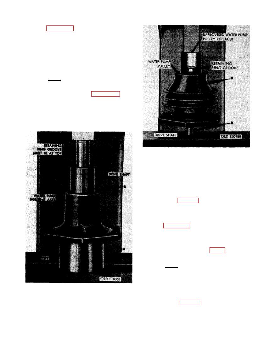 (4) Figure 129. (A) Position water pump
housing assembly on a piece of- pipe
which has an inside diameter large
enough to clear the installed water pump
seal. (B) Start drive shaft bearing into
housing bore and press in housing until
bearing area of shaft passes retaining
ring groove.
Note. The drive shaft bearing can be
pressed past the retaining ring groove.
If this occurs, press drive shaft out of
housing as shown in figure 123 until
bearing is flush with groove. Drive shaft
must be installed with water pump pul-
ley retaining ring groove toward pulley
side of housing.
PULLEY ON DRIVE SHAFT USING IM-
PROVISED PULLEY REPLACER.
(5) Refer to figure 122 and reverse the in-
structions to install water pump drive
shaft retaining ring.
(6) Figure 130. (A) Position. the impeller
end of water pump shaft on a press
plate as shown. (B) Start water pump
pulley on drive shaft and press it into
position using the improvised water
pump pulley replacer (fig. 31).
Note. Opening on side of water pump
pully replacer allows mechanic to tell
when retaining ring groove has just
cleared the pulley, allowing for install-
ation of the ring.
(7) Refer to figure 119 and reverse the se-
DRIVE SHAFT IN WATER PUMP
quence of instructions to install water
HOUSING ASSEMBLY.
pump pulley retaining ring.
99
|
|
Privacy Statement - Press Release - Copyright Information. - Contact Us |
