 |
|||
|
|
|||
|
Page Title:
FIGURE 51. REMOVING OR INSTALLING TURBOSUPERCHARGER ASSEMBLY (LATE MODEL ENGINES) |
|
||
| ||||||||||
|
|
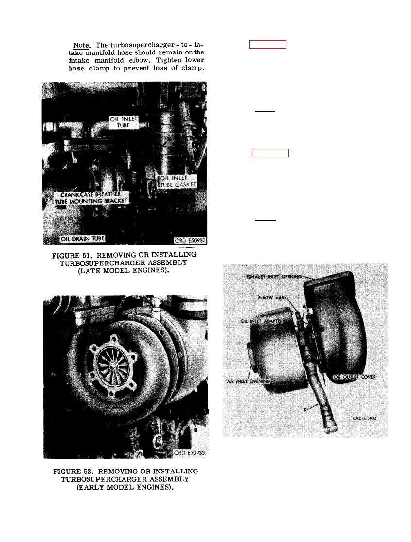 (9) Figure 52. (A) Remove four 3/8- inch
self-locking nuts securing turbosuper-
charger to exhaust manifold. (B) Re-
move turbosupercharger assembly. (C)
Remove anddiscard turbosupercharger
gasket.
Note. The turbosupercharger -to-in-
take manifold hose should remain onthe
intake manifold elbow. Tight en lower
hose clamp to prevent loss of clamp.
(l0) Figure 53. (A) Loosen 9/16-inch plain
nut and remove tube-to- adapter elbow
assembly. (B) Remove and discard 15/32
id x 5/64 thk preformed packing from
elbow. (C) Remove turbosupercharger
oil drain hose from oil outlet cover.
Note. Plug and seal all turbosuper-
charger openings to prevent entrance
of foreign material.
TURBOSUPERCHARGER OIL DRAIN
HOSE AND OIL INLET ELBOW AS-
SEMBLY (EARLY MODEL ENGINES).
65
|
|
Privacy Statement - Press Release - Copyright Information. - Contact Us |
