 |
|||
|
|
|||
|
|
|||
| ||||||||||
|
|
 turned to the "ON" position, and the engine
engine mounting bracket hold-down studs and
started and operated not over 1200 revolutions
securely tighten engine-to-container engine
per minute (RPM) until observed fuel return is
m o u n t i n g flange. Tighten the six nuts that secure
p u r g e d of diesel fuel and the system filled with
the transmission adapter support flange.
preservative oil.
P o s i t i o n parts that have been removed from the
engine and tape or strap separately to engine
intakes, breathers, etc. shall not be sealed.
and support cross members.
Note. The engine requires no special de-
Note. Engines that are being returned for
preservation procedures to be made serviceable.
r e b u i l d should be securely mounted in container.
T h e loose parts that have been removed from the
8-12. Engine Installation
e n g i n e should also be secured by some means to
prevent shifting and causing additional damage
a. T h e t u r b o s u p e r c h a r g e r o u t e r s h r o u d p l a t e
to the engine and container during transit.
assembly and the intermediate shroud plate on
both the right and left bank must be removed, in
o r d e r to provide proper clearance for the engine
i n the container. On engines which have the oil
f i l l e r tube installation at the rear of the engine,
t h e upper portion of the two piece tube must be
d i s c o n n e c t e d and removed. Refer to figure 4-18
t h r o u g h 4-21 and 4-23 for removal of the shroud
plates and upper portion of the oil filler tube.
The parts that have been removed from the
engine, must be packaged separately to prevent
damage and secured to the engine or container
prior to assembling container halves.
b. Inspect engine thoroughly for loose or
missing parts or components. Check to be sure
engine has been properly identified as having
Figure 8-10. Transmission adapter -
b e e n preserved for storage. Install the two engine
installed view.
m o u n t i n g brackets on the three centrally located
oil pan mounting bosses on either side of the
9) mounted on the side wall of the container,
engine (fig. 8-8). Install the six bolts from the
with eight bags of desiccant (MIL-D-3464, 16
u n d e r s i d e of the oil pan and assemble a washer
unit bags, Class 1). Apply sealing compound
and a nut on each bolt. Tighten securely. The
conforming
to
MIL-I-8660
on
the
sealing
engine mounting brackets must be installed on
gasket and position the sealing gasket on the
t h e engine prior to installing engine in container.
c o n t a i n e r flange. Assemble the upper section of
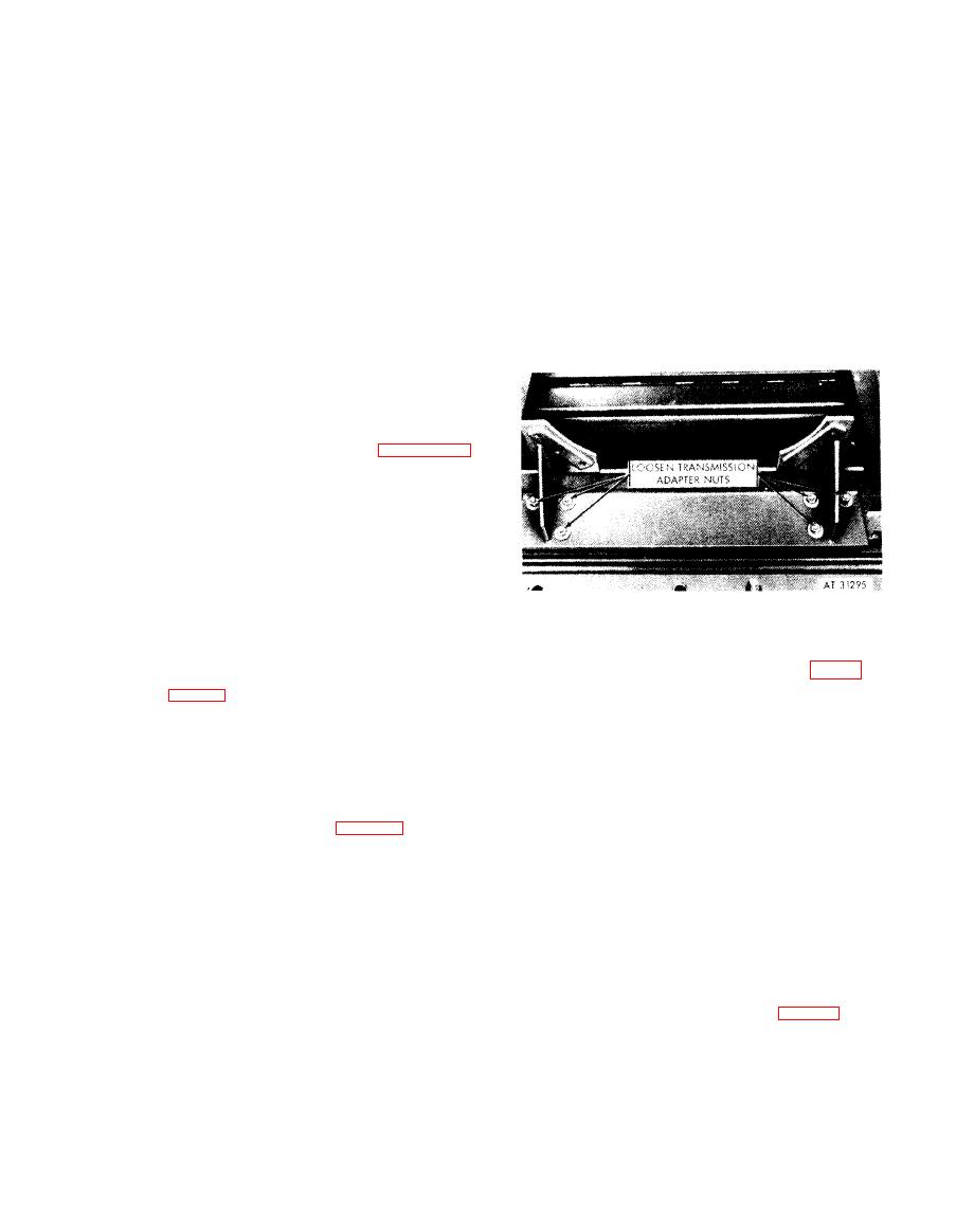
c. L o o s e n b u t d o n o t r e m o v e t h e s i x n u t s
the container to the lower section. Torque
securing transmission adapter support flange to
tighten assembly bolts to 90-105 lbs ft.
the container cross member (fig. 8-10). Using
e. W h e n a s s e m b l y i s c o m p l e t e , p r e s s u r i z e t h e
engine lifting multi-leg sling - 4910-919-2884,
c o n t a i n e r 5 to 7 psi of dehydrated air and allow
carefully guide the engine into position on the
container to stand for a minimum of twelve
e n g i n e mounting bracket hold-down studs in the
hours to be sure air pressure is maintained.
container. Aline the rear transmission adapter
f. Periodic inspection of containers that are to
s u p p o r t flange screw holes with the screw holes
b e stored for extended periods of time should be
i n the engine transmission adapter and install six
m a d e to determine if the pressure of moisture is
1 in. screws and lock washers starting with the
evident in the container. This is determined by
u p p e r right and left screw holes on the support
the humidity indicator located in the recessed
f l a n g e . Install one 1 in. screw and lock washer
insert on the end of the container (fig. 8-7).
in the remaining screw hole in the lower center of
Under moisture-free conditions, the indicator
t h e support flange. Tighten all screws securely.
will show blue in color. As the presence of
Install the four nuts and lock washers on the
8-17
|
|
Privacy Statement - Press Release - Copyright Information. - Contact Us |
