 |
|||
|
|
|||
|
Page Title:
Figure 6-101. Removing or installing auxiliary and main oil filter attaching parts. |
|
||
| ||||||||||
|
|
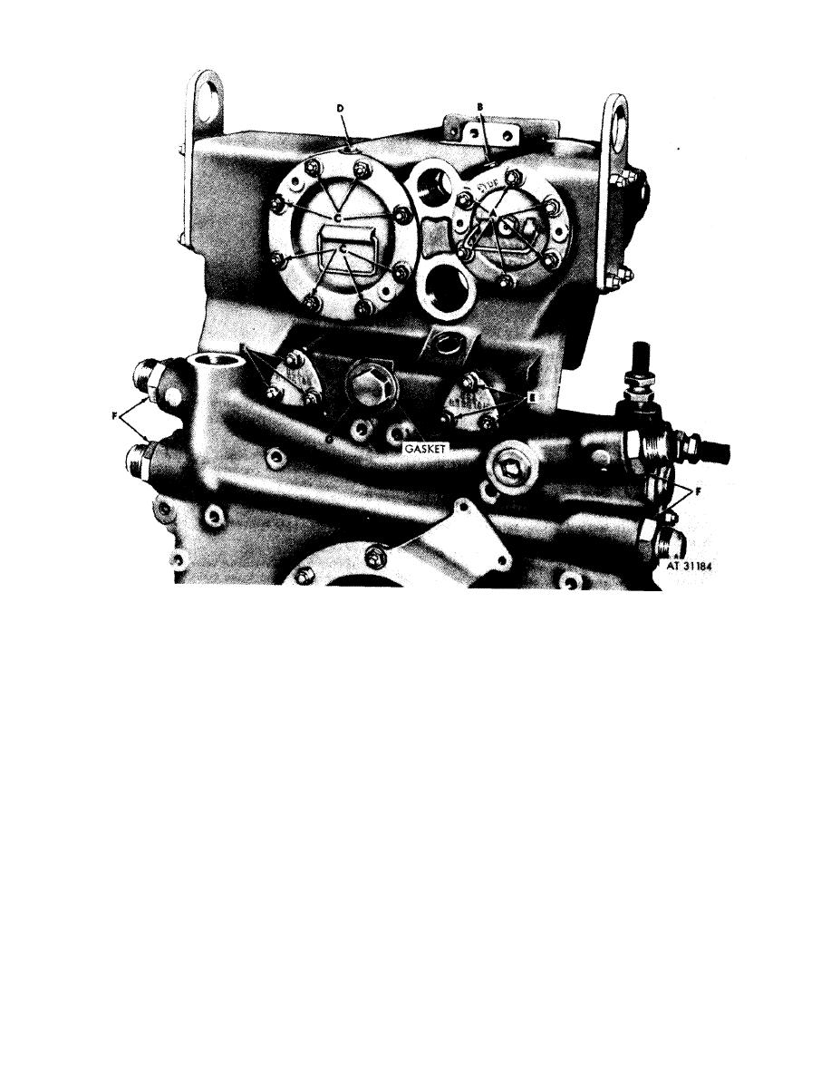 7. Remove core hole plug (G) and gasket from housing.
Remove
1. Remove six self-locking nuts (A) and flat washers
Discard gasket.
attaching main oil filter assembly to damper and oil
Install
1. Position a new gasket on core hole plug (G) and install
filter housing.
2. Loosen main oil filter stop bolt (B) several turns and
plug in damper and oil filter housing.
pull filter from housing until it engages stop bolt.
2. Install four oil cooler tube nipples (F) in housing.
3. Position new drain cover gaskets and two oil drain
Collect oil in a suitable container.
covers on housing. Install six self-locking nuts (E) and
Note. It may be necessary to use two 5 / 16-
flat washers securing drain covers to housing.
24 x 1-inch jack screws in the puller screw
4. With auxiliary oil filter positioned in housing, tighten
h o l e s to break the gasket seal between the filter
auxiliary oil filter stop bolt (D) to 125 inch-pounds
flange and the housing.
5. Install eight self-locking nuts (C) and flat washers
3. Remove eight self-locking nuts (C) and flat washers
attaching auxiliary oil filter to housing.
securing filter in housing.
4. Loosen auxiliary oil filter stop bolt (D) and drain filter
6. With main oil filter assembly positioned in housing
as described in step 2, above.
tighten main oil filter stop bolt (B) to 125 inch-pounds
5. Remove six self-locking nuts (E) and flat washers
7. Install six self-locking nuts (A) and flat washers
attaching two oil drain covers to housing. Remove
covers and discard drain cover gaskets.
securing filter in housing.
6. Remove four oil cooler tube nipples (F) from housing.
filter attaching parts.
6-99
|
|
Privacy Statement - Press Release - Copyright Information. - Contact Us |
