 |
|||
|
|
|||
|
Page Title:
Figure 5-178. Removing or installing crankshaft and connecting rod assemblies using crankshaft and connecting rod sling-4910-... |
|
||
| ||||||||||
|
|
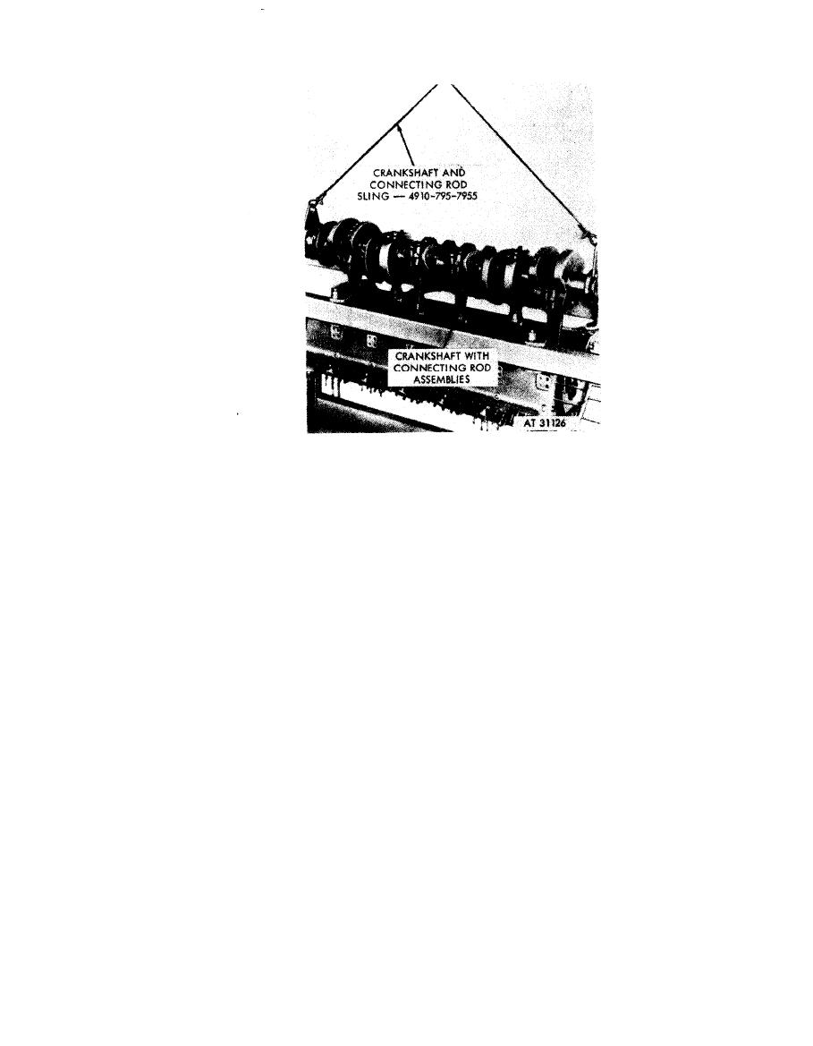 tubes over main bearing studs for protection. If such
Note. Exercise
care
when
removing
or
in-
tubes are not available, cover studs with industrial tape.
stalling crankshaft assembly to prevent damage
2. Install crankshaft and connecting rod assemblies in
to the main bearing cap studs and crankshaft
crankcase as shown using a suitable hoist. Guide the
journals.
connecting rods through the cylinder mounting holes
and past the connecting rod protectors.
Remove
1. Remove crankshaft with connecting rod assemblies
Note. The connecting rods are installed on the
installed as shown, using a suitable hoist.
crankshaft in pairs. The connecting rod of each
2. Place crankshaft assembly on suitable "V" blocks
pair toward the flywheel end (rear) serves the left
with crankshaft resting on bearing journals.
Install
bank cylinders; the connecting rod toward the
1 . Before installing crankshaft and connecting rod
front of the engine serves the right bank.
assemblies in crankcase, place cardboard or plastic
Figure 5-178. Removing or installing crankshaft and connecting rod
assemblies using crankshaft and connecting rod
sling- 4 9 1 0 - 7 9 5 - 7 9 5 5 .
5-104
|
|
Privacy Statement - Press Release - Copyright Information. - Contact Us |
