 |
|||
|
|
|||
|
Page Title:
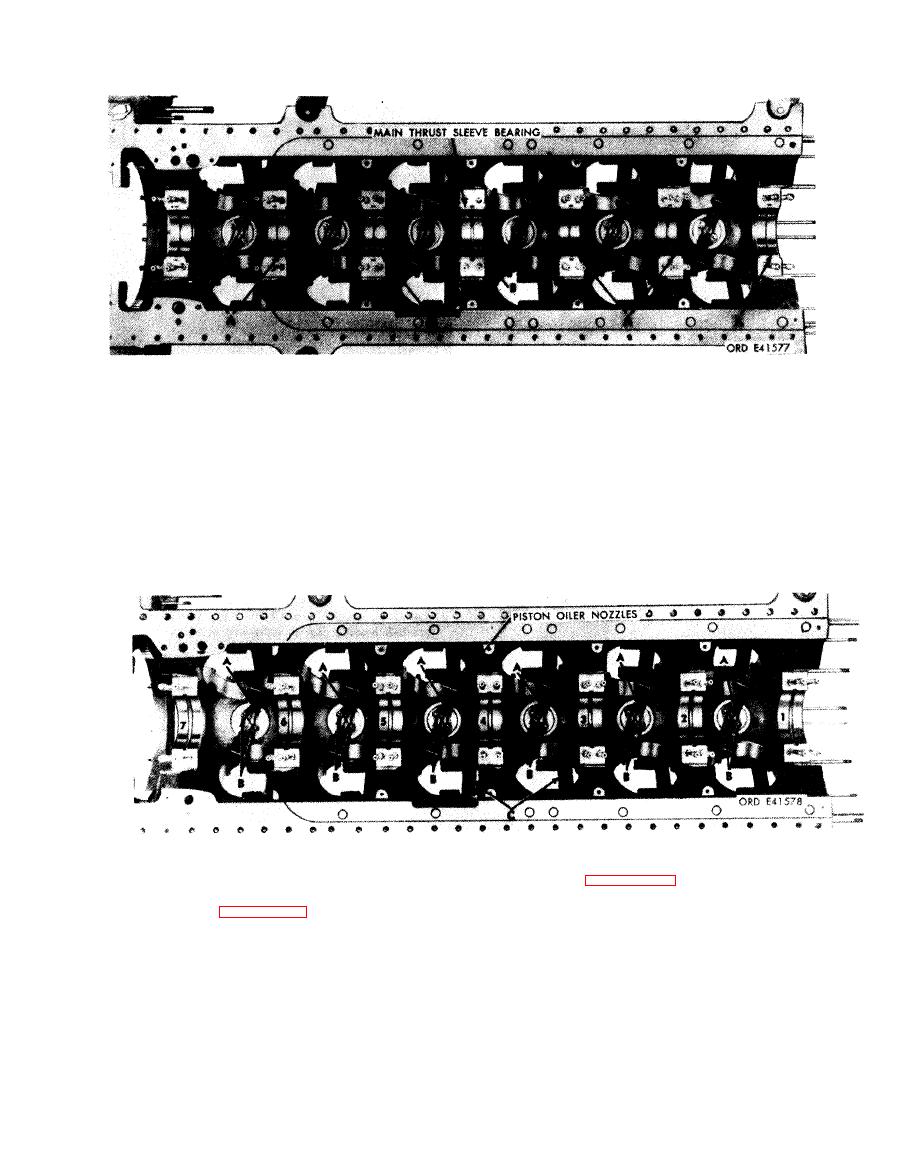
Figure 5-179. Removing or installing upper main sleeve bearing halves |
|
||
| ||||||||||
|
|
 Install
Remove
1. Remove six upper main sleeve bearing halves (A)
Note. Numbers 1 through 7 indicate main
f r o m bearing bores in crankcase assembly. Mark
bearing sleeve locations beginning from the
respective locations of bearings on the back of bearing
front.
half using a grease pencil; e.g., "l-case", "2-case", etc.
2. Remove upper main thrust sleeve bearing half(B) and
1. Install
upper main thrust sleeve bearing half (B)
mark as "4-case" for identification.
marked
"4-case" in main bearing bore.
2. Install
six upper main sleeve bearing halves (A) in
bearing
bores in accordance with respective location
marks.
Install
Remove
1 . Refer to figure 5-147 and install 12 crankcase
1. Cut locking wire (A). Remove 12 slotted nuts (B) and
protectors - 4910-795-7951 (C).
remove six piston oiler nozzle assemblies.
2. Position six piston oiler nozzle assemblies in crankcase
2 . Refer to figure 5-147 and remove 12 crankcase
and install 12 slotted nuts (B) securing nozzle
protectors - 4910-795-7951 (C).
a s s e m b l i e s to crankcase. Install locking wire (A)
securing slotted nuts (B).
5-105
|
|
Privacy Statement - Press Release - Copyright Information. - Contact Us |
