 |
|||
|
|
|||
|
Page Title:
Figure 5-58. Removing or installing oil level indicator tube plate-engines with relocated oil filler tube installation. |
|
||
| ||||||||||
|
|
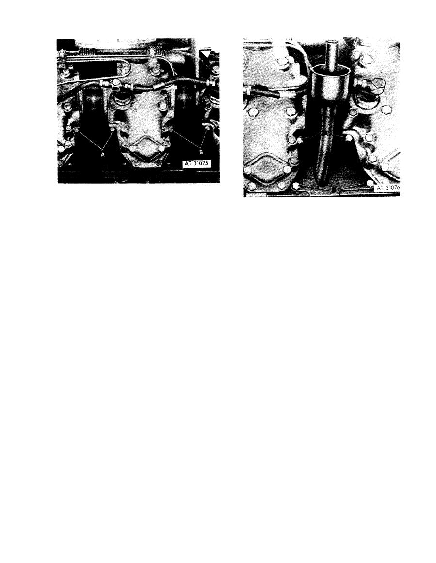 Remove
1. Remove two machine screws (A) and lock washers
and remove cylinder head plate at oil filler tube.
2. Remove two machine screws (B) and lock washer-e
and remove cylinder head plate at oil level indicator
Remove
tube.
1. Remove two machine screws (A) and lock washers
Install
and remove oil level indicator tube plate.
1. Position cylinder head plate at oil level indicator tube
2. Remove two machine screws (B) and lock washers
position. Install two machine screws (B) and lock
attaching oil level indicator tube cylinder plate.
washers securing plate.
Install
2. Position cylinder head plate at oil filler tube position.
1. Install two machine screws (B) and lock washers
Install two machine screws (A) and lock washers
securing oil level indicator tube cylinder plate.
securing plate.
2. Position oil level indicator tube plate and install two
machine screws (A) and lock washers securing plate.
Figure 5-57. Removing or installing cylinder
head plates at oil filler and oil level
Figure 5-58. Removing or installing oil level
indicator tubes-- engines with
indicator tube plate-engines with
splash pan installation.
relocated oil filler tube installation.
5-31
|
|
Privacy Statement - Press Release - Copyright Information. - Contact Us |
