 |
|||
|
|
|||
|
Page Title:
Fuel Filters, Throttle Linkage, Front and Rear Shrouds, and Oil Filler and Indicator Tubes |
|
||
| ||||||||||
|
|
 Remove
Install
1. Remove 18 nuts (A) and lock washers attaching
1. Install six new intake manifold tube gaskets (B) on
intake tubes to cylinders. Remove manifold, manifold
studs.
heater, and turbosupercharger air outlet elbow as a
2. Position manifold, manifold heater, and tur-
unit.
bosupercharger air outlet elbow as. a unit on cylinder
2. Remove and discard six intake manifold tube gaskets
studs. Install 18 nuts (A) and lock washers securing
intake tubes to cylinders.
(B).
Note. The right and left intake manifolds are
removed or installed in the same manner.
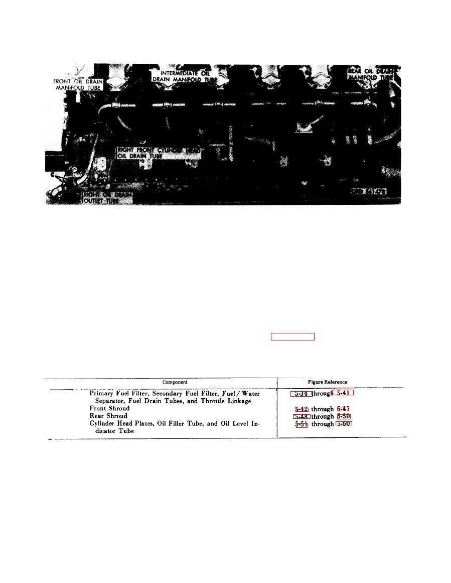
5-7. Fuel Filters, Throttle Linkage, Front
Refer to Table 5-4 for illustrations and
a n d Rear Shrouds, and Oil Filler and
disassembly instructions. Figure references are
Indicator Tubes
listed in the table.
Table 5-4. Fuel Filters, Throttle Linkage, Front and Rear Shrouds,
and Oil Filler and Indicator Tubes
5-18
|
|
Privacy Statement - Press Release - Copyright Information. - Contact Us |
