 |
|||
|
|
|||
|
Page Title:
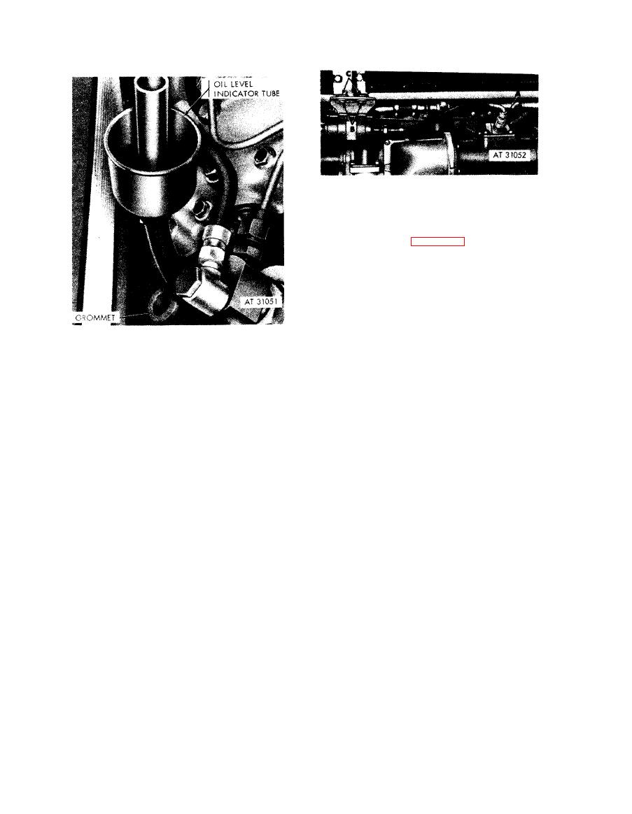
Figure 5-10. Removing or installing manifold heater ignition unit-right side |
|
||
| ||||||||||
|
|
 Remove
N o t e . With the exception of the early engine
o i l filler and oil level indicator tube retaining
straps (A and B, fig. 4-131), the oil coolers,
s u p p o r t beams, and upper cover frames on each
side of the engine are removed in the same
m a n n e r . For instructional purposes, removal of
the right oil coolers, support beams, upper cover
frames and frame support brackets are described
i n the following instructions.
1. Disconnect manifold heater spark plug cable (A).
2. Cut locking wire and remove two screws (B), spacers,
and flat washers attaching ignition unit bracket to oil
tube shroud plate oil drain hose
coolers. Remove ignition unit, bracket, and cable.
g r o m m e t - installed view-engines with oil
3. Remove grommets (C) from bracket- Replace
filler and indicator with splash pan drain.
damaged grommets.
Install
1. Position grommets (C) in bracket.
2. Position ignition unit, bracket, and cable on oil
coolers. Install two screws (B), spacers, and flat
washers securing ignition unit bracket to oil coolers.
Lock wire screws securely.
3. Connect manifold heater spark plug cable (A) to
spark plug.
heater ignition unit-right side.
5-6
|
|
Privacy Statement - Press Release - Copyright Information. - Contact Us |
