 |
|||
|
|
|||
|
Page Title:
Figure 4-58. Removing fuel injection pump and preformed packing-diaphragm coupler |
|
||
| ||||||||||
|
|
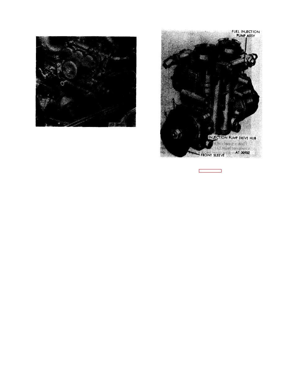 1. Remove fuel injection pump (A) from mounting base.
2 . Remove and discard preformed packing (B) from
mounting base.
3. Remove bolt (C) and washer.
Note. Plug or cap fuel and oil openings in
pump.
1. Place a metal rod in one of the sleeve alinement
Figure
4-58.
Removing
fuel
injection
pump
holes (A) as shown in figure 4-63. Coupler sleeve must
and
preformed
packing-diaphragm
coupler.
be in rigid position to remove nut.
2. Remove plain nut (B) and lock washer.
Note. The nut, lock washer, and key are part
of the pump assembly and must be installed on
pump after hub is removed.
Caution: The splined coupler halves are a
matched set. Damage or wear to the sleeve or
hub of either coupling half requires the
replacement of a complete coupler assembly.
Figure
4-59.
Removing
fuel
injection
pump
front splined coupler sleeve nut and
lock washer.
4-31
|
|
Privacy Statement - Press Release - Copyright Information. - Contact Us |
