 |
|||
|
|
|||
|
Page Title:
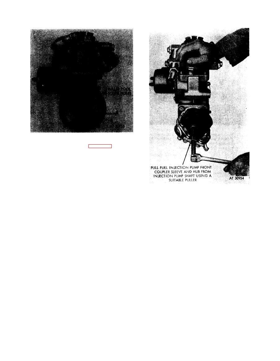
Figure 4-61. Removing fuel injection pump splined coupler sleeve and hub |
|
||
| ||||||||||
|
|
 1. Place a metal rod in one of the injection pump coupler
alinement holes (A) as shown in figure 4-64. Injection
pump coupling must be in a rigid position to remove
nut.
2. Remove plain nut (B) and lock washer.
Note. The nut, lock washer, and key are part
of the pump assembly and must be installed on
the pump after the coupler sleeve is removed.
Figure
4-60.
Removing
fuel
injection
pump
diaphragm coupler nut and lock washer.
Figure 4-61. Removing fuel injection pump
splined coupler sleeve and hub.
4-32
|
|
Privacy Statement - Press Release - Copyright Information. - Contact Us |
