 |
|||
|
|
|||
|
|
|||
| ||||||||||
|
|
 TM 9-2520-270-34
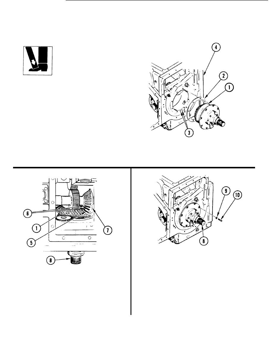
WARNING
D o not drop input bevel
assembly. Personnel can be
injured.
8 3 . ROTATE TRANSMISSION SO BOTTOM
SIDE IS UP.
84. INSTALL INPUT BEVEL ASSEMBLY (1)
WITH NEW SHIM(S) (2) REMOVED IN
STEP 75.
a. Slide shim(s) (2) onto assembly (1) and
aline screw holes and oil holes (3).
Shim(s) go on one way.
b, Coat assembly (1) with transmission
oil.
c. Push assembly (1) into housing (4)
until all holes are alined.
86. INSTALL EIGHT WASHERS (9) AND
SCREWS (10).
87. USING 1/2-lNCH DRIVE TORQUE
WRENCH, TORQUE EIGHT SCREWS (10)
85. ALINE PAINTED TOOTH (5) ON
TO 25-30 ft-lb (3-4 mkg).
INPUT BEVEL ASSEMBLY (1) WITH
TWO PAINTED TEETH (6) ON
88. ROTATE INPUT GEARSHAFT (8)
PINION (7).
TO SEAT BEARINGS.
a . Looking into bottom of transmission,
a. Rotate input gearshaft (8) an equal
rotate input shaft (8) until tooth (5)
number of turns right, then left, to
is between two teeth (6).
seat bearings.
4-112
|
|
Privacy Statement - Press Release - Copyright Information. - Contact Us |
