 |
|||
|
|
|||
|
|
|||
| ||||||||||
|
|
 TM 9-2520-270-34
WARNING
Input bevel assembly is
heavy and awkward. Install
slowly or input bevel
assembly can fall and
injure personnel.
CAUTION
Use care when pushing input bevel assembly
into transmission housing. Equipment can be
damaged.
NOTE
It is necessary to look through bottom of
transmission to see gear touch fixture.
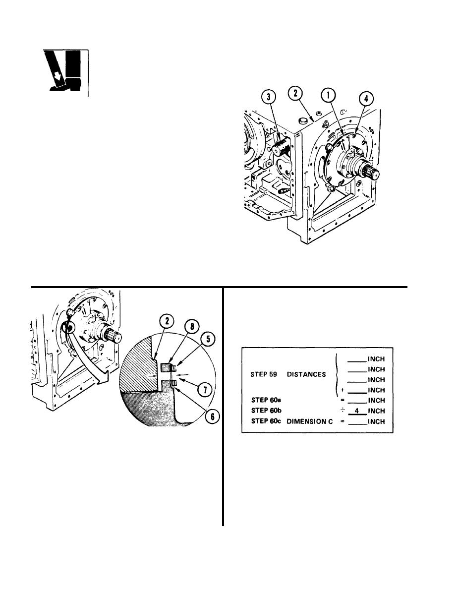
58. POSITION INPUT BEVEL
ASSEMBLY (1) INTO HOUSING (2).
a. Coat outside of assembly (1) with
transmission oil.
b. Using plastic-faced hammer, tap
assembly (1) into housing (2) until
contact with fixture (3) is made.
c. Do not allow screw holes (4) to
aline with holes in housing (2).
59. MEASURE DISTANCE FROM
WASHERS (5) TO HOUSING (2).
a.
Place same two washers (5) on same
spot faces (6) marked in step 55.
b.
Using depth gage, measure distance
60. OBTAIN DIMENSION C.
from washers (5) to housing (2) through
a . Add four distances.
screw hole (7) of mounting flange (8).
b. Divide result of step 60a by four.
c.
Repeat step 59b for three other spot
faces (6).
c. Record result as dimension C.
4-106
|
|
Privacy Statement - Press Release - Copyright Information. - Contact Us |
