 |
|||
|
|
|||
|
Page Title:
Position left output housing assembly |
|
||
| ||||||||||
|
|
 TM 9-2520-249-34&P
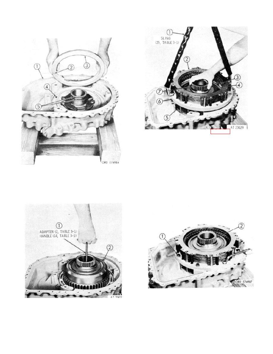
23. Using lifting sling (1)(25, table 3-1) install brake
assembly (2) steer clutch assembly (5), and
spacer assembly (6) as a unit. Aline the bolt
holes in the spacer with those in the housing.
Grasp the sling with one hand and, while
rotating sun gear (7) back and forth, move the
assembly up and down by squeezing the sling
strands together. This movement allows the
21. Position left output housing assembly (1 ) on
internal splines of the steer clutch disks to
wood blocks. Aline hole (2) in piston (3) with
engage the splines on the output clutch hub and
anti-rotation pin (4) in housing (1) and install
thus seat properly. Two slots in oil baffle (4)
piston assembly 131 with its seal rings. Make
must be engaged with two keys (3) positioned
certain two seal rings (5) are in place on the
180 degrees apart. Remove lifting sling (1).
output sleeve.
24. Install eight 3/8-16 x 21/4-inch, self-locking
bolts (1) and eight plain washers. Tighten the
22. Using handle and adapter (1), (14 and 2. table
bolts to 36 to 43 pound feet torque.
(3-1) install left output clutch assembly (2) into
the output housing. Remove the handle and
adapter.
8-13
|
|
Privacy Statement - Press Release - Copyright Information. - Contact Us |
