 |
|||
|
|
|||
|
|
|||
| ||||||||||
|
|
 TM 9-2520-249-34&P
bolts (2) and install remaining two bolts.
Tighten bolts evenly to 36 to 43 pound feet
torque (refer to step 6, below). Remove rope
sling (3).
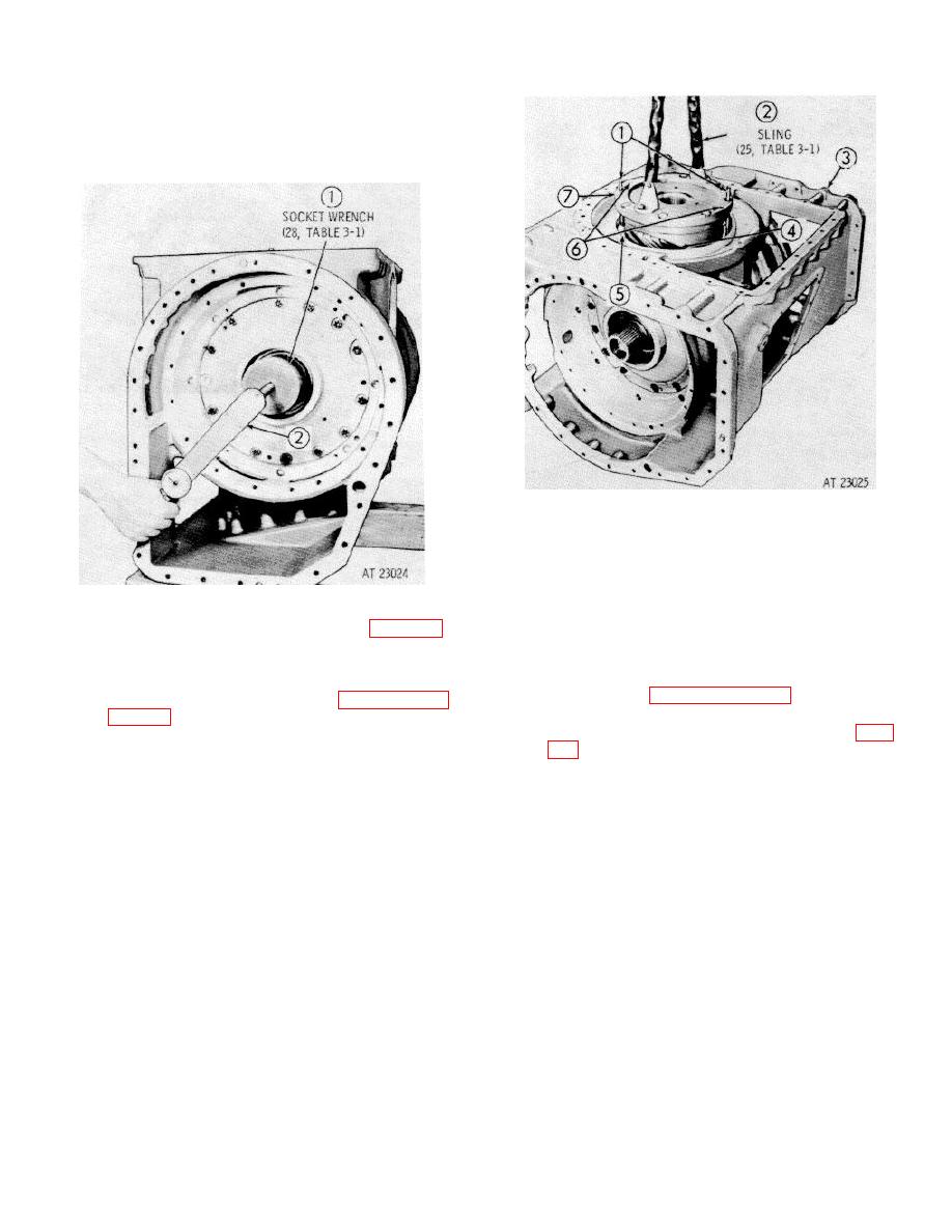
7 Position bevel gear housing (3), rear downward,
on blocks. Install two 3/8-16 x 4-inch headless
guide bolts (1) in opposite holes of gear
assembly mounting face. Install the proper
shims (5) into the recess at the front of the
6. Check the torque required to rotate the cross
housing, alining the shims to index with bolt
shaft while tightening the left bearing retainer
holes. Two holes in the shims must aline with
bolts. Use socket wrench (1), (28, table 3-1)
largest threaded holes (6) in bevel drive gear
and a pound inch torque wrench (2) to rotate the
assembly (7).
shafts. If torque exceeds 2 pound inches, or if
NOTE
shaft end play exceeds 0.0015 inch when
Refer to paragraph 8-5, above, for
retainer bolts are tight, refer to paragraphs 8-6
shimming instructions
and 8-7, above.
Using two 3/8-16 bolts, attach sling (2), (25, table
bevel drive gear assembly into the bevel gear
housing. The open side of the bevel gear carrier
(4) must face the right side of the bevel gear
housing. Mesh the drive gear teeth with those of
the driven gear while installing. Remove the
guide bolts and lifting sling.
8-8
|
|
Privacy Statement - Press Release - Copyright Information. - Contact Us |
