 |
|||
|
|
|||
|
Page Title:
Section XV. STEER COOLANT CHECK VALVE RETAINER ASSEMBLY-REPAIR |
|
||
| ||||||||||
|
|
 TM 9-2520-249-34& P
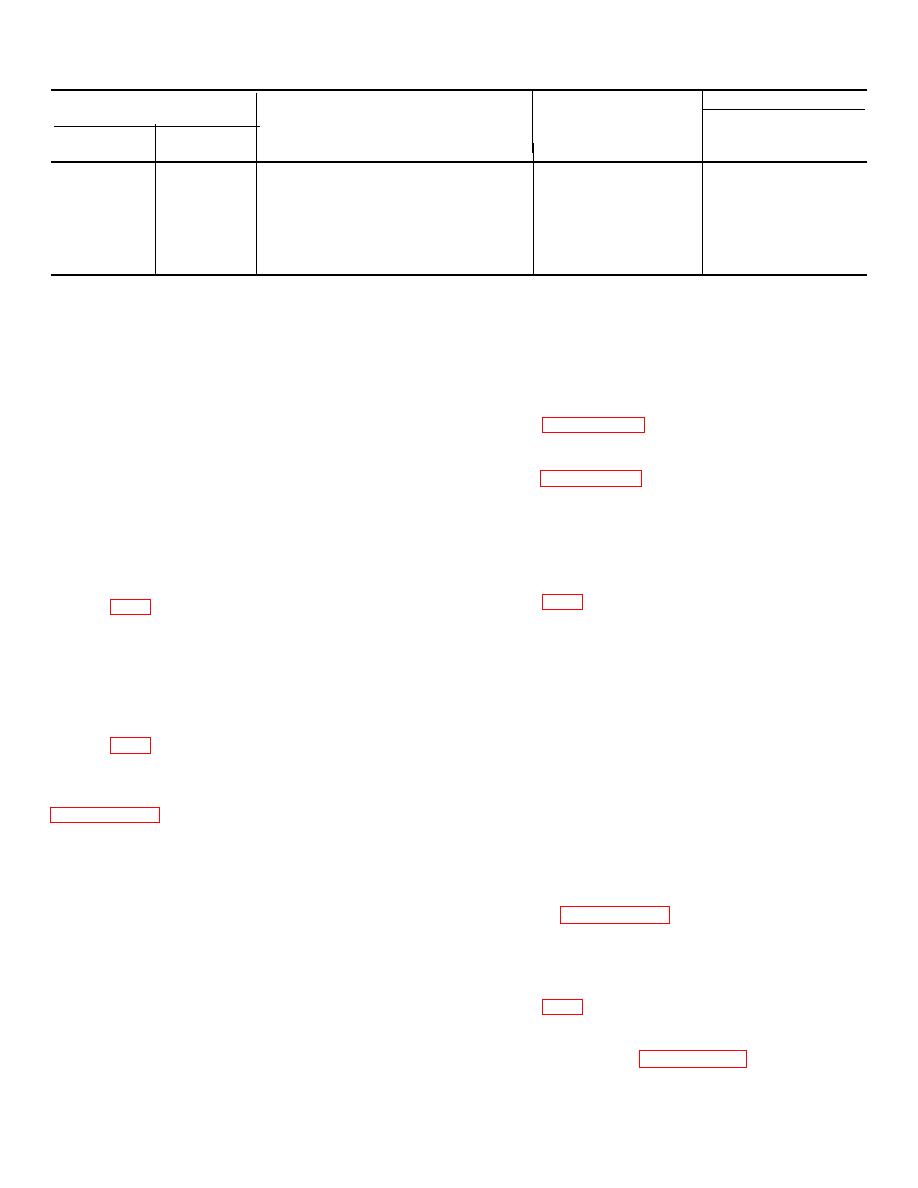
Table 7-12. Repair Standards (Bevel Drive Gear)--Continued
Wear limit
Reference
Size and fit
DS/GS
Foldout
Item
Point of measurement
of new parts
maintenance
5
36a
Inside diameter of bearing inner race ...
4.2500 to 4.2510
*
5
38a
Outside diameter at bearing surface of .
4.2515 to 4.2525
4.2512
support
5
36a,
Fit of bearing inner race on support .....
0.0005T to 0.0025T
38a
*Replace when worn beyond new dimensions.
Section XV. STEER COOLANT CHECK VALVE
RETAINER ASSEMBLY-REPAIR
disk (30) from which the valve was removed.
NOTE
Right and left assemblies use
7-88. Cleaning
identical parts and require identical
Refer to paragraph 5-2 for cleaning recommendations.
repair procedures; however, the
assembly relation of parts differs for
7-89. Inspection and Repair
left and right. They must be kept
Refer to paragraph 5-3 for general inspection and repair
separate so that each will be
recommendations.
assembled
properly
in
the
transmission. Only the right side
7-90. Repair Standards
parts are referenced in the following
These components do not involve repair standards.
procedures.
7-91.
Assembly
7-86.
Description
The steer coolant check valve (53) is a two-diameter,
a. If any of the 11 guide pins (49) were
step-type, spool-shape valve. Its larger diameter end
removed from retainer (50) for replacement, install new
enters a bore in steer coolant check valve retainer
pins. Press each pin until it projects 1.to 1.80 inch above
assembly (48). The smaller diameter end passes
the flat side of the retainer.
through a hole in reverse-range reaction clutch disk
b. If alinement pin (51) was removed from
(30), where it is retained by a spring-type pin (52).
retainer (50) for replacement, install a new pin into the
7-87- Disassembly
same hole from the flat side of the retainer. Press the
pin in unit it projects 1.76 to 1.80 inch above the flat side
of the retainer.
a. Remove Teflon sealring (56) and expander
c. If valve (53) was removed from reaction
(55) from retainer assembly (48) as outlined in
disk (30) for replacement, install a new valve into the
same hole, from the same side of the plate as removed
b. Do not remove alinement pin (51) or guide
(marked at disassembly). Install retaining pin (52)
pins (49) from retainer (50) except for replacement. If
through valve (53), letting it protrude equal lengths at
alinement pin (51) is removed, mark the hole from
each side of the valve stem.
which it is removed for proper replacement.
d. Install expander (55) and sealring (56), as
c. Remove steer coolant check valve (53)
outlined in paragraph 7-55, preceding.
only if it needs replacement by pulling out pin (52). To
insure proper assembly, mark the hole and the side of
Section XVI. REVERSE-RANGE PLANETARY CARRIER ASSEMBLY-REPAIR
NOTE
7-92. Description
The right and left carrier assemblies
Reverse-range planetary carrier assembly (36) is 6
are identical, therefore, the right
pinion type carrier assembly with rollers (39.5) for each
assembly only is described in the
pinion (39.4). Refer to paragraph 2-11.
following procedures.
7-23
|
|
Privacy Statement - Press Release - Copyright Information. - Contact Us |
