 |
|||
|
|
|||
|
|
|||
| ||||||||||
|
|
 TM 9-2520-249-34&P
7-41.
Repair Standards
from intermediate-range carrier assembly (30).
c. Remove the snapring and bearing
repair standards.
assembly from the planetary carrier (fig. 7-8).
(32), driving them toward the inside of the carrier. Refer
a. Chill spindles (31.8) for approximately 1
to figure 7-9.
hour in dry ice prior to installing in planetary carrier (32).
b. Grease the bore of a pinion (31.3) with a
liberal amount of oil-soluble grease.
c. Install a spacer (31.2) and thrust washer
(31.1) on one end of planetary pinion (31.3).
d. Install 24 rollers (31.6) around the pinion
bore wall.
e. Install another spacer (31.4) and thrust
washer (31.5) on the second end of pinion (31.3).
f.
Insert the pinion with spacers, rollers and
washers into its location in carrier (32). Using alinement
tool of replacer (22, table 3-1), aline the pinion and its
components with the carrier spindle bore (fig. 7-10).
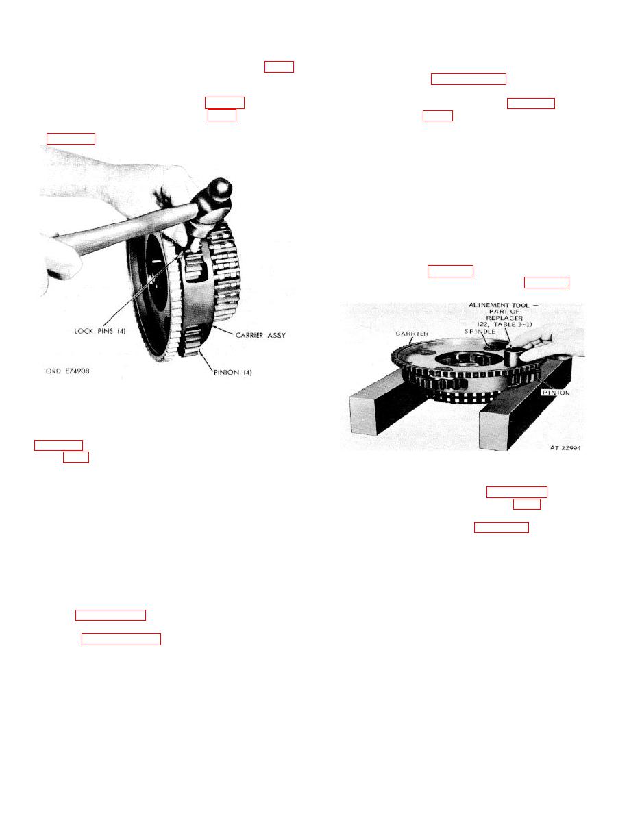
Figure 7-9. Removing spindle lock pins from
intermediate range planetary carrier assembly.
e. Using a spindle of replacer assembly (22,
(31.8, FO-4) from carrier (32).
Figure 7-10. Alining pinion assembly in intermediate-
f.
Remove eight thrust washers (31.1 and
range planetary carrier.
31.5), eight spacers (31.2 and 31.4), 96 rollers (31.6)
g. Using replacer
(22,
install
and four pinions (31.3), keeping each set of components
planetary carrier pinion spindle (31.8, FO-4). Press the
with its pinion.
spindle flush with, to 0.010 inch below, the spindle bore
NOTE
surface of the carrier. Refer to figure 7-11.
The pinions are a matched set. Keep each
pinion and its component parts in a separate
container. If one pinion must be replaced, all
four must be replaced with a matched set of
four pinions.
7-39. Cleaning
Refer to paragraph 5-2 for cleaning recommendations.
7-40. Inspection and Repair
Refer to paragraph 5-3 for inspection and repair
recommendations.
7-10
|
|
Privacy Statement - Press Release - Copyright Information. - Contact Us |
