 |
|||
|
|
|||
|
|
|||
| ||||||||||
|
|
 TM 9-2520-249-34& P
screws (95), for replacement only, by pressing them out.
7-9.
Cleaning
b. Stator and Components (FO-3).
Refer to paragraph 5-2 for cleaning recommendations.
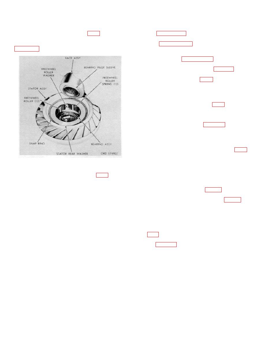
(1) Remove
freewheel
roller
race
7-10. Inspection and Repair
assembly (24) from stator assembly (19). Refer to
Refer to paragraph 5-3 for inspection and repair
recommendations.
7-11. Repair Standards
repair standards.
7-12. Assembly
were removed for replacement; install new screws with
the flat sides of the head toward the center of pump
(97). Press each screw in until it bottoms on the pump
(or balance weight when used).
b. Stator and Components (FO-3)
(1) If freewheel cam (27) was removed
from stator assembly (19) for replacement of either part,
install the cam into the stator assembly as marked when
disassembled. As an aid, refer to figure 7-3, a rear view
of the stator assembly, and note that the freewheel roller
and spring pockets and deeper at the clockwise end
(spring end) of the pocket. Also note that the rear of the
stator has a counterbore new its internal splines.
(2) Place stator assembly (19, FO-3),
front end up, and install freewheel roller washer (21),
stator thrust washer (20), larger inside diameter end
first, and retain it with retaining ring (18).
Figure 7-3. Removing freewheel race .assembly.
(3) Turn stator assembly (19) over, rear
(counterbored) end up, and install bearing race thrust
(2) Remove 12 rollers (26, FO-3) and 12
washer (22).
springs (25).
(4) Install the bearing assembly, roller
(3) Remove retaining ring (30), washer
side up, into the stator assembly (fig. 7-3).
(29) and washer (28) from stator assembly (19).
(5) Install the freewheel race assembly,
(4) Remove bearing assembly (23) and
sleeve end first, into the stator assembly (fig. 7-3). Be
bearing race thrust washer (22) from stator assembly
sure that the sleeve extends through the bearing
(19).
assembly and its race.
(5) Remove retaining ring (18), stator
(6) Install 12 freewheel rollers and 12
thrust washer (20), and freewheel roller thrust washer
freewheel roller springs. Springs go in the clockwise
(21).
(deeper) end of each pocket.
(6) Do not remove the sleeve from
(7) Install freewheel roller thrust washer
freewheel roller race assembly (24).
(28 FO-3), stator cam roller washer (29), smaller outside
(7) Do not remove cam (27) except for
diameter first, and retain it with retaining ring (30).
parts replacement. If the cam is to be removed, first
Refer to figure 7-4.
note the relations of the cam to stator assembly (19) to
insure correct installation of cam to stator.
c. Turbine Assembly. The turbine assembly
is of riveted construction and is assembled and
balanced at the factory. If replacement is necessary, it
is replaced as an assembly.
7-3
|
|
Privacy Statement - Press Release - Copyright Information. - Contact Us |
