 |
|||
|
|
|||
|
Page Title:
CHAPTER 5. REPAIR OF POWER TAKEOFFS |
|
||
| ||||||||||
|
|
 TM 9-2520-246-34
CHAPTER 5
REPAIR OF POWER TAKEOFFS
Section I. DESCRIPTION, OPERATIONAL AND DATA (MODEL WN-7-28)
5-1. General. This chapter contains the rebuild
forward and backward on the shaft by the shifter fork
instructions for power takeoff models WN-7-28,
(Z). The other is the output shaft high speed gear (BB)
WND-7-28, and P-136-C.
which is free on the output shaft (H) and is in
constant mesh with the input gear (P). The sliding
gear (AA) is splined to the output shaft (H) and may
takeoff model WN-7-28, is designed for mounting on
be meshed with the spur teeth of the reverse gear
an SAE standard 6-hole or 6-stud power takeoff
(FF), with the spur teeth of the input gear (P) (for low
opening. The unit is designed to be mounted on the
speed operation) or may act as a clutch gear to couple
left or right side of the driving mechanism. The shifter
the output shaft high speed gear (BB) to the output
shaft extends through each end of the case so that the
shaft (H).
shifting control linkage may be attached at either end.
The output shaft extends from the front of the case
c. Shifter Fork. The shifter fork (Z) is attached to
the shifter shaft (A) by a capscrew. The fork engages
and is provided with a woodruff key for mounting the
winch propeller shaft companion flange. Boots are
the circumferential groove on the sliding gear (AA).
installed over the ends of the shifter shaft to protect
the surface of the shaft. The input gear of the power
takeoff is a cluster composed of a helical gear which is
constantly in mesh with the helical gear of the
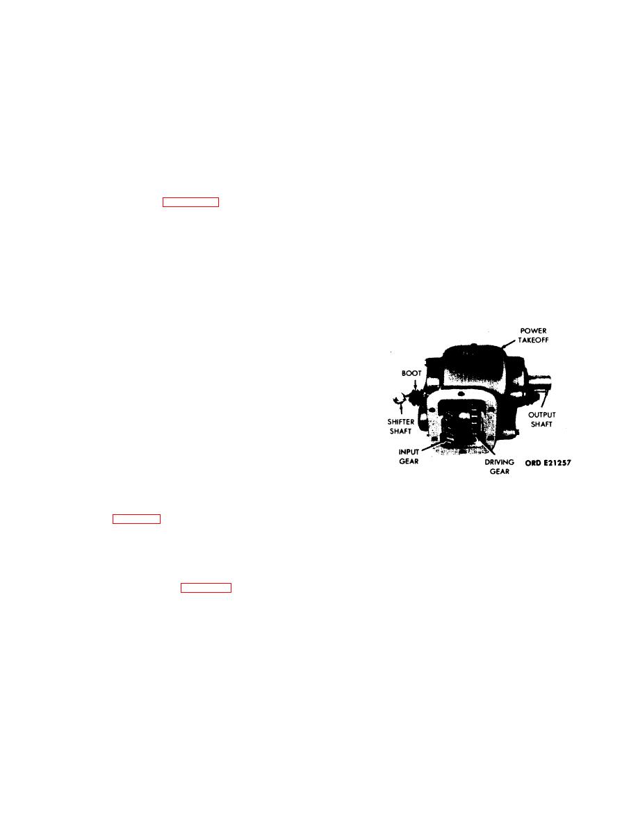
transmission reverse idler gear, and the driving gear
which is of spur tooth construction. The power
takeoff has two speeds forward, neutral, and one
speed in reverse. A shifting mechanism provides for
selection of the desired speed and direction of rotation
of the output shaft. The shifting mechanism in neutral
position disengages the output shaft gears from the
driving gear.
5-3. Operation.
NOTE
Figure 5-1. Power Takeoff Model WN-7-28.
The reference letters in parentheses pertain
to figure 5-2.
5-4. Data.
a. Input Gear. The helical input gear (P) is in
National stock number . . . . . . . . . . 252040-7061137
constant mesh with the helical gear of the
Ordnance number . . . . . . . . . . . . . . . . . . . . . . . 7061137
transmission reverse-idler gear and therefore, is in
Manufacturer . . . . . . . . . . . Spicer Div. - Dana Corp.
constant rotation when the transmission is engaged.
Model . . . . . . . . . . . . . . . . . . . . . . . . . . . . . . . . WN-7-28
(Refer to transmission, Chapter 3.) The input gear (P)
Type . . . . . . . . . . . . . . . . . . . . . . . . . . . . . . Heavy-duty
is installed on a nonrotating input gearshaft (L) and is
Speeds . . . . . . . . . . . . . . . . . . . . . . 2 forward, 1 reverse
mounted on the input gear roller bearings (N). The
Drive . . . . . . . . . . . . . . . . . . . . . . . . . . . . . Transmission
shaft is pressed into the housing and secured with a
Input gear . . . . . . . . . . . . . . . . . . . . . . . . . . . . . Helical
cotter pin. A thrust washer (M) is located at each end
Output shaft . . . . . . . . . . . . . . . . . 1 in. dia;5/16 in.
of the input gear. The helical tooth portion of the
keyway
input gear (P) is in constant mesh with the reverse
Bearings:
gear (FF) which is installed on the reverse gearshaft
Output shaft . . . . . . . . . . . . . . . . . . . Two-ball type
(JJ) and secured with the reverse gear pin (EE). The
Input shaft . . . . . . . . . . . . . . . . . . . . Two-roller type
reverse gearshaft rotates in two supporting bearings
Reverse gear . . . . . . . . . . . . . . . . . . Two-roller type
(GG and FF).
Horsepower delivered:
100 rpm . . . . . . . . . . . . . . . . . . . . . . . . . . . . . . . . . 2.7
b. Output Shaft. The output shaft (H) is supported
500 rpm . . . . . . . . . . . . . . . . . . . . . . . . . . . . . . . . . . 13
in the housing on two ball bearings (F and S). Two
1000 rpm . . . . . . . . . . . . . . . . . . . . . . . . . . . . . . . . . 27
gears are installed on the output shaft (H). One is the
Gear pitch . . . . . . . . . . . . . . . . . . . . . . . . . . . . . . 7/9 in.
output shaft sliding gear (AA) which is moved
Backlash (allowable) . . . . . . . . . . . . . . . . . . . . 0.008 in.
5-1
|
|
Privacy Statement - Press Release - Copyright Information. - Contact Us |
