 |
|||
|
|
|||
|
Page Title:
Figure 3-21. Removal of Companion Flange. |
|
||
| ||||||||||
|
|
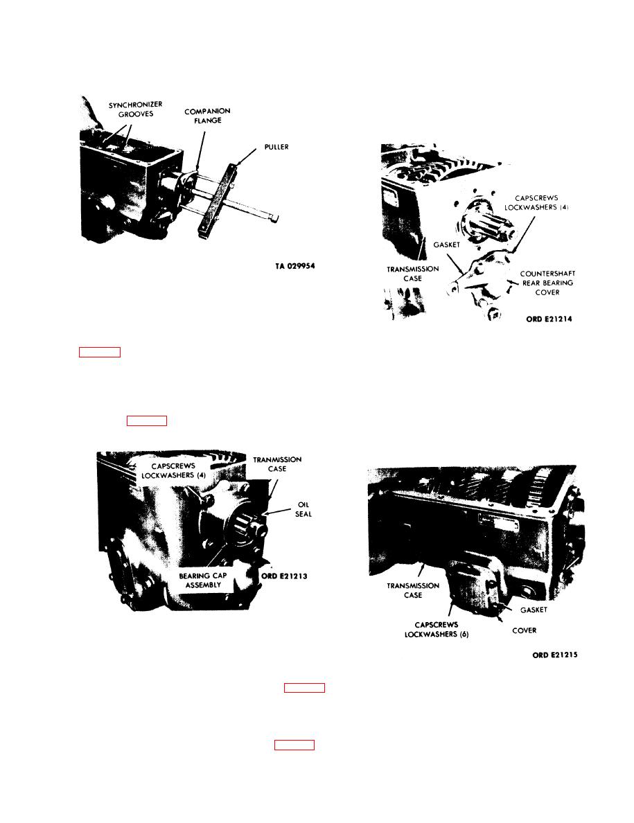 TM 9-2520-246-34
gasket. Discard the gasket. Slide the input shaft and
bearing assembly straight out from the transmission.
Keep input shaft-to-mainshaft roller bearings together
for use in assembly purposes.
Figure 3-21. Removal of Companion Flange.
d. Mainshaft Rear Bearing Cap Assembly. Remove
the four capscrews and lockwashers securing the
bearing cap assembly to the transmission case. (See
Figure 3-23. Removal of Countershaft Rear
Bearing Cover.
and gasket. Discard the gasket.
NOTE
e. Countershaft Rear Bearing Cover. Remove the
four capscrews and lockwashers securing the
On installation, coat the roller bearings
countershaft rear bearing cover to the transmission
with grease, artillery and automotive
case. (See fig. 3-23.) Remove the countershaft rear
(GAA) MIL-G-10924. This practice
bearing cover and gasket. Discard the gasket.
prevents the roller bearings from dropping
out of place during assembly.
Figure 3-22. Removal of Mainshaft Rear Bearing
Cap Assembly.
f. Power Takeoff Cover Opening. Remove the six
capscrews and lockwashers securing the power takeoff
Figure 3-24. Removal of Power Takeoff Opening Cover.
opening cover to the transmission case. (See fig. 3-24.)
Remove the cover and gasket. Discard the gasket.
h. Mainshaft Rear Bearing. With the use of a block
of wood, drive the mainshaft rearward to force the
g. Input Shaft Bearing Cap. Remove the four
rear bearing from the transmission case. (See fig. 3-
capscrews and lockwashers securing the input shaft
26.) Use a universal puller to remove the rear bearing
bearing cap to the transmission case. (See fig. 3-25.)
from the mainshaft.
Remove the input shaft bearing cap, spacer, and
3-13
|
|
Privacy Statement - Press Release - Copyright Information. - Contact Us |
