 |
|||
|
|
|||
|
|
|||
| ||||||||||
|
|
 TM 9-2520-238-34
EQUIPMENT DESCRIPTION AND DATA -- Continued
0002 00
TRANSFER GEARCASES
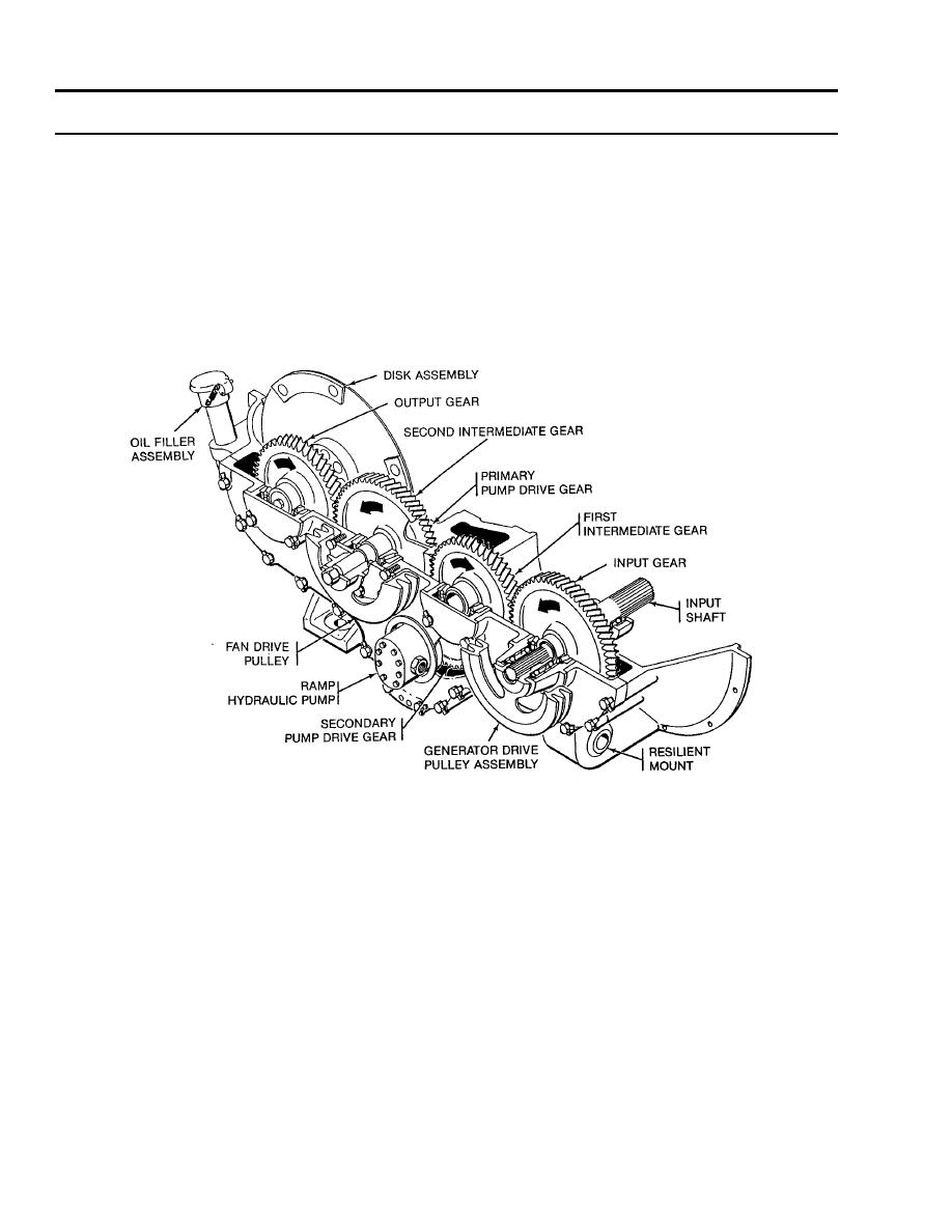
TRANSFER GEARCASE TORQUE PATH. The transfer gearcase delivers variable torque, generated at the input shaft by the
engine and transferred through a series of four helically meshed gears, to the output gear and disk assembly. Any gear (input,
first intermediate, second intermediate, or output gear) may drive an externally mounted power takeoff (pulley) assembly.
Two additional gears (primary and secondary pump-drive gears) are coupled in series with the second intermediate gear to
provide torque to externally mounted oil and hydraulic pumps.
GEAR ROTATIONS. Torque applied to the input shaft causes the shaft and input gear to rotate in a counterclockwise direction.
The first intermediate gear rotates clockwise; the second intermediate gear and primary pump-drive gear rotate
counterclockwise; and the output gear, output disk assembly, and secondary pump-drive gear rotate clockwise.
Typical Transfer Gearcase Torque Path
REMOTE CONTROL DISCONNECT LEVER. A manually operated remote control engine disconnect lever disengages the
input shaft from the gear train to stop torque flow through the transfer gearcase. This enables the engine to operate with very
little load for easier cold weather starting.
HOUSING AND COVER. The housing and cover of the transfer gearcases are made of aluminum and machined as a unit.
They must be replaced as a matched pair.
0002 00-2
|
|
Privacy Statement - Press Release - Copyright Information. - Contact Us |
