 |
|||
|
|
|||
|
Page Title:
EQUIPMENT DESCRIPTION AND DATA |
|
||
| ||||||||||
|
|
 TM 9-2520-238-34
EQUIPMENT DESCRIPTION AND DATA
0002 00
EQUIPMENT FUNCTIONAL DESCRIPTION
COOLING FAN RIGHT ANGLE DRIVES
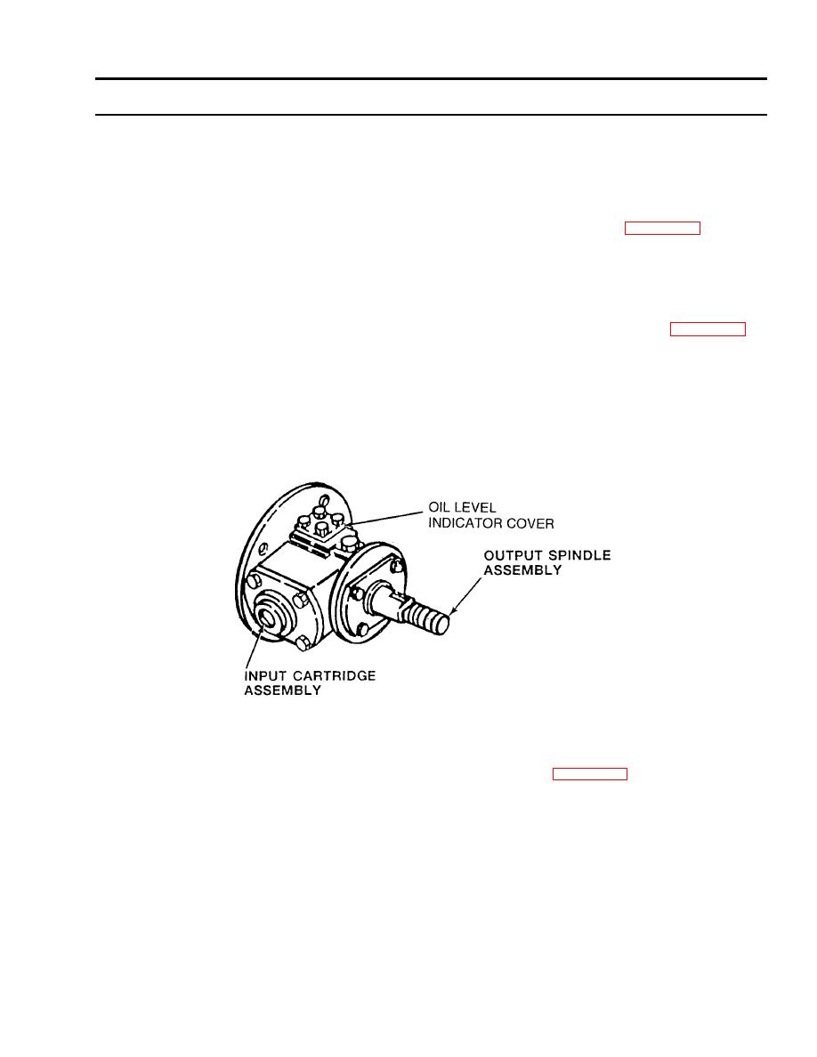
RIGHT ANGLE DRIVE A. Each cooling fan right angle drive A consists of an input cartridge assembly and an output spindle
assembly encased in a magnesium or aluminum housing. When installed in a carrier, see Table 11, (WP 0001 00), the right
angle drive receives torque through an input gearshaft and, by means of a 26tooth spiral bevel gear in the cartridge assembly
and a 27tooth spiral bevel gear in the spindle assembly, drives a rotor (fan) mounted on the output shouldered shaft. The
bevel gear and bevel gearshaft are a matched set and are mounted on matched sets of ball bearings. The gears and bearings
are adjusted by inserting or removing laminated shims.
RIGHT ANGLE DRIVES A AND B. Each cooling fan right angle drive A consists of an input cartridge assembly and an output
spindle assembly encased in a magnesium or aluminum housing. When installed in a carrier, see Table 11, (WP 0001 00),
the right angle drive receives torque through an input gearshaft and, by means of a 26tooth spiral bevel gear in the cartridge
assembly and a 27tooth spiral bevel gear in the spindle assembly, drives a rotor (fan) mounted on the output shouldered
shaft. The bevel gear and bevel gearshaft are a matched set and are mounted on matched sets of ball bearings. The gears and
bearings are adjusted by inserting or removing laminated shims. When viewed from the input gearshaft, the gearshaft rotates
counterclockwise. The output shouldered shaft rotates clockwise and has left-hand threads at the lower end which act as an oil
pump. Oil is forced down the outside of the shaft, through the threads and up the center of the shaft to the spindle assembly.
A hollow pin in the shaft allows oil to spray against the gears. Some oil continues up the inside of the shaft to lubricate the
upper bearings. Angle drive A has a plastic oil level indicator cover. Angle drive B has a visible liquid sight indicator glass.
Cooling Fan Right Angle Drive
RIGHT ANGLE DRIVE C. Cooling fan right angle drive C consists of an input cartridge assembly and an output spindle
assembly encased in an aluminum housing. When installed in a carrier, see Table 11, (WP 0001 00), the right angle drive
receives torque through an input shouldered shaft and, by means of a 28tooth spiral bevel gear in the cartridge assembly and
a 21tooth spiral bevel pinion gear in the spindle assembly, drives a cooling fan mounted on the shaft and bearing assembly.
The bevel gear and bevel pinion gear are a matched set. This gear arrangement allows higher fan speed than angle drives A
and B, with more cooling air flow. Like angle drives A and B, the shaft and bearing assembly act as an oil pump to lubricate
the gears and bearings. When viewed from the input shaft, the shouldered shaft and bevel gear rotates clockwise, and the fan
shaft and bearing and pinion gear rotates clockwise. The gears and bearings are adjusted by inserting or removing laminated
shims. Angle drive C has a glass oil level sight indicator like right angle drive B.
0002 00-1
|
|
Privacy Statement - Press Release - Copyright Information. - Contact Us |
