 |
|||
|
|
|||
|
Page Title:
Figure 1-5. Fuel System Schematic |
|
||
| ||||||||||
|
|
 TM 55-4920-424-13&P
Figure 1-5. Fuel System Schematic
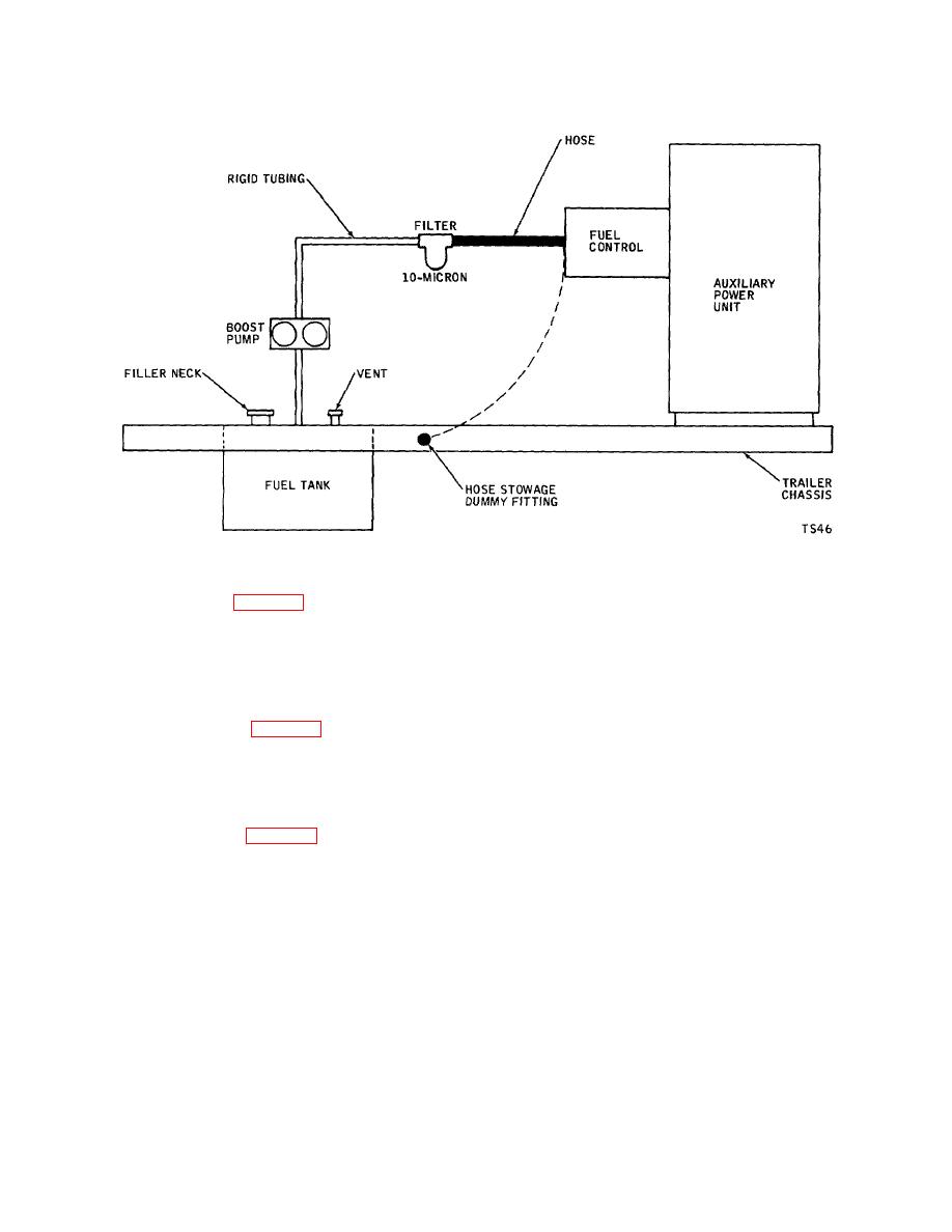
1-23. FUEL TANK. (See figure 1-3.)
1-24. The fuel tank is a 40-gallon-capacity aluminum tank built into the trailer frame. The tank has a four-inch diameter
filler neck, an overboard vent, and a drain fitting for draining condensation or for draining the tank prior to shipping or
storage. A standpipe and fitting connects to the fuel boost pump through rigid tubing. The tank filler cap incorporates a
dipstick fuel indicator.
1-25. BOOST PUMP. (See figure 1-3.)
1-26. The fuel boost pump is an electric motor-driven pump bolted to a support bracket on the right side of the trailer.
The boost pump draws fuel from the fuel tank and routes it through the fuel filter to the fuel control on the APU. A
minimum of 5 psig fuel boost pressure is sufficient to ensure fuel flow to the fuel system of the APU.
1-27. FUEL FILTER. (See figure 1-3.)
1-28. A replaceable-element, low-pressure fuel filter is bolted to a support bracket on the right side of the trailer. A
pressure relief valve within the filter head assembly is set to relieve at 10 to 12 psi differential pressure. The filter provides
10-micron filtration of the fuel before entry into the fuel system of the APU.
1-8
|
|
Privacy Statement - Press Release - Copyright Information. - Contact Us |
|
|
Integrated Publishing, Inc. - A (SDVOSB) Service Disabled Veteran Owned Small Business
|

