 |
|||
|
|
|||
|
Page Title:
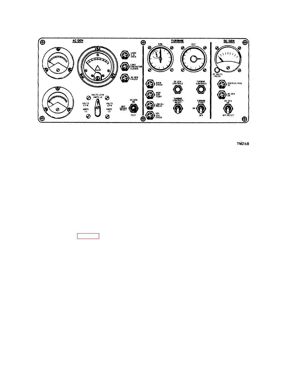
Figure 1-4. Console Instrument Panel |
|
||
| ||||||||||
|
|
 TM 55-4920-424-13&P
Figure 1-4. Console Instrument Panel
1-17. THERMOCOUPLE.
1-18. The thermocouple is stowed on the left side of the engine support frame. When in use, the thermocouple is
installed on the top side of the APU exhaust outlet. The thermocouple probe projects into the exhaust stream and senses
exhaust gas temperature at the chromel-alumel junction. A small voltage is generated and converted to an indication
(degrees centigrade) on the exhaust temperature indicator during engine operation.
1-19. TACHOMETER GENERATOR.
1-20. The tachometer generator is stowed inside the hinged door of the control console. When in use, the tachometer
generator is mounted in tandem with the speed switch on the APU, and generates a small voltage which is converted to
an indication on the engine speed indicator instrument during engine operation.
1-21. FUEL SYSTEM. (See figure 1-5.)
1-22. The fuel system consists of a fuel tank, an electric motor-driven fuel boost pump, a disposable-element type fuel
filter, and connecting rigid and flexible plumbing. The filter and boost pump are mounted on a support bracket, which is
bolted to the engine support frame on the trailer. All components provide a complete and independent fuel system for the
operation of the APU while on the trailer. A flexible hose, connected to a dummy fitting during storage, connects the fuel
system to the APU.
1-7
|
|
Privacy Statement - Press Release - Copyright Information. - Contact Us |
|
|
Integrated Publishing, Inc. - A (SDVOSB) Service Disabled Veteran Owned Small Business
|

