 |
|||
|
|
|||
|
|
|||
| ||||||||||
|
|
 TM 55-4920-411-13&P
Press START/STOP, RESET switch a second time.
RESULT: SECONDS display shall stop.
Press START/STOP, RESET switch
c. If SECONDS display does not stop, see Trouble-
RESULT: SECONDS display shall increase in 1 sec-
shooting Table 4-3.
ond increments to 99 and then repeat.
Press START/STOP, RESET switch a third time.
a. If SECONDS display does not increase, check
START/STOP, RESET switch for continuity while
RESULT: SECONDS display shall reset to 00.
pressing switch. If switch iS open, replace switch S5 (67,
d. If SECONDS does not reset, see Troubleshooting
b. If START/STOP, RESET switch checks good. use
e. Set POWER switch to OFF,
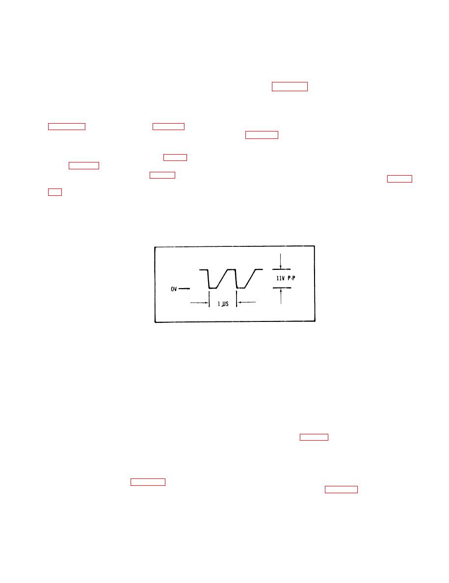
an oscilloscope and frequency counter to check wave-
form between test points 1 (+) and 3 (-), fig 4-7. If wave-
f. Connect frequency counter and oscilloscope 10 to 1
form (fig 4-13) is absent, replace defective associated
positive lead to J2 pin A and negative lead J2 to pin B,
using adapter and two test leads as required in fig 4-3.
out-of-adjustment, adjust to 1 megahertz with RIO (fig
i. Disconnect lead from TPl on Signal Generator
g. Set POWER switch to ON.
Board and reconnect to J2 pin A. Reconnect frequency
counter.
h. Set FUNCTION switch to 5% and FREQ ADJ to 0
j. Set FUNCTION switch and FREQ switch to each
position. Frequency counter will indicate between 4.058
settings as listed in table 4-7. Frequency counter will in-
and 4.175 ms and disconnect frequency counter. Wave-
dicate within limits specified. If not, repeat technique (h)
form on oscilloscope should be a square wave at approx-
above setting FUNCTION switch to 110% and FREQ
imately 8 volts peak to peak. If not, remove lead from J2
ADJ to +5 readjust R10 for 1.0 MHz. Adjusting for mid-
pin A and reconnect to TP1 on Signal Generator Board
point between low and high settings. If indications are
and adjust RIO for 1.0 MHz. If indications cannot be
out of tolerance, replace defective components, see fig
met, see Troubleshooting Table 4-3 as applicable and
FO-1 and Troubleshooting Table 4-3.
replace defective associated components, fig FO- 1.
4-21
|
|
Privacy Statement - Press Release - Copyright Information. - Contact Us |
