 |
|||
|
|
|||
|
Page Title:
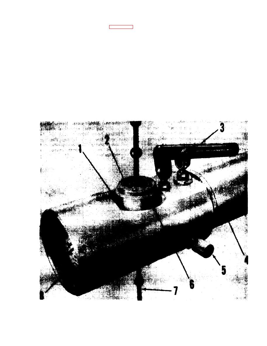
Figure 4-2. Hydraulic Pump Assembly. |
|
||
| ||||||||||
|
|
 TM 55-4920-201-14
limited by a piston stop washer and
The hydraulic pump assembly contains hydraulic
retaining ring (1). With the ram piston
fluid and is ready for use when removed from the
against this stop, further actuation of
balancing kit storage case and installed on the hoist
the pressure pump will result in a build-
arm structure of the stand assembly. Operation is as
up of internal pressure which may
follows:
cause damage to the load indicating
gage (8) or to internal pump parts.
a. To raise (hoist) a suspended load, turn the
Never operate the pump beyond an
pump valve (5) counterclockwise to the limit of its
indicated load of 800 pounds.
travel. This closes the ram bypass and directs
pressure to the ram cylinder. Actuate the pump
b. To lower a suspended load, turn the pump
handle (3) to raise the ram piston (6) to desired
valve clockwise to gradually open the ram bypass
level within the piston's normal travel of ap-
and unload the ram piston. For more rapid descent,
proximately 1 inches.
the valve may be turned clockwise as desired up to
the limit of its travel.
CAUTION
Upward travel of the ram piston is
Figure 4-2. Hydraulic Pump Assembly.
4-3
|
|
Privacy Statement - Press Release - Copyright Information. - Contact Us |
