 |
|||
|
|
|||
|
|
|||
| ||||||||||
|
|
 TM 55-1930-208-24
3-39. VALVE OPERATING MECHANISM - Continued.
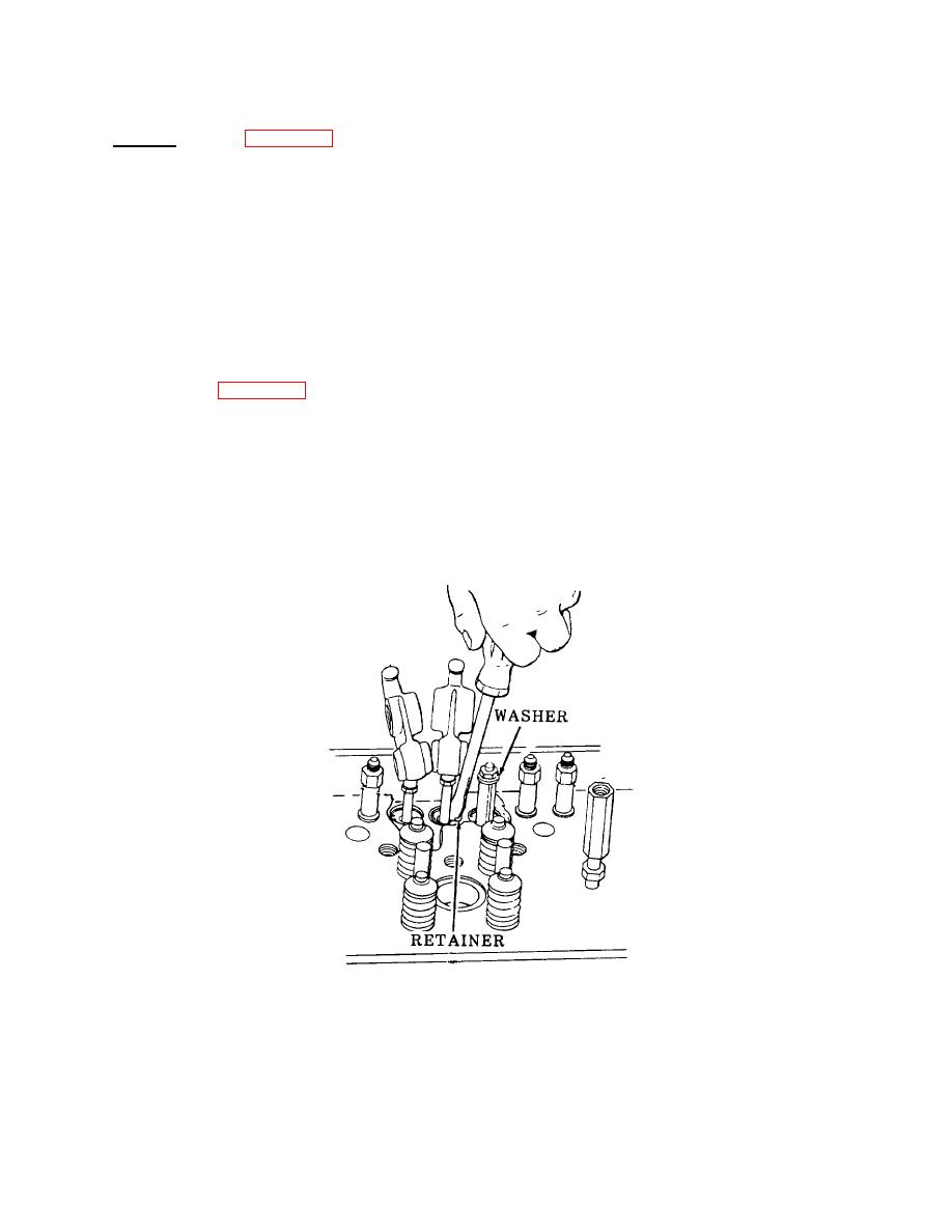
a. Removal. (Refer to figure 3-79).
NOTE
When removing cam followers and associated parts, tag them so they can be installed in their original
location.
(1)
Remove push rod locknut.
(2)
Install remover J3092-01, a flat washer, and push rod locknut, with the lower end of the tool resting on
the upper seat.
(3)
Thread nut down to compress spring.
(4)
Refer to figure 3-80 and remove three spring retainers (1).
(5)
Remove locknut, flat washer, and remover.
(6)
Remove three upper spring seats (2), three springs (3), three lower spring seats (4), and three push rods
(5).
(7)
Remove two screws (6), two lockwashers (7), and cam follower guide (8).
(8)
Remove three cam followers (9).
Figure 3-79. Removing Push Rod from Upper Side of Cylinder Head Using Tool J3092-01.
3-138
|
|
Privacy Statement - Press Release - Copyright Information. - Contact Us |
