 |
|||
|
|
|||
|
Page Title:
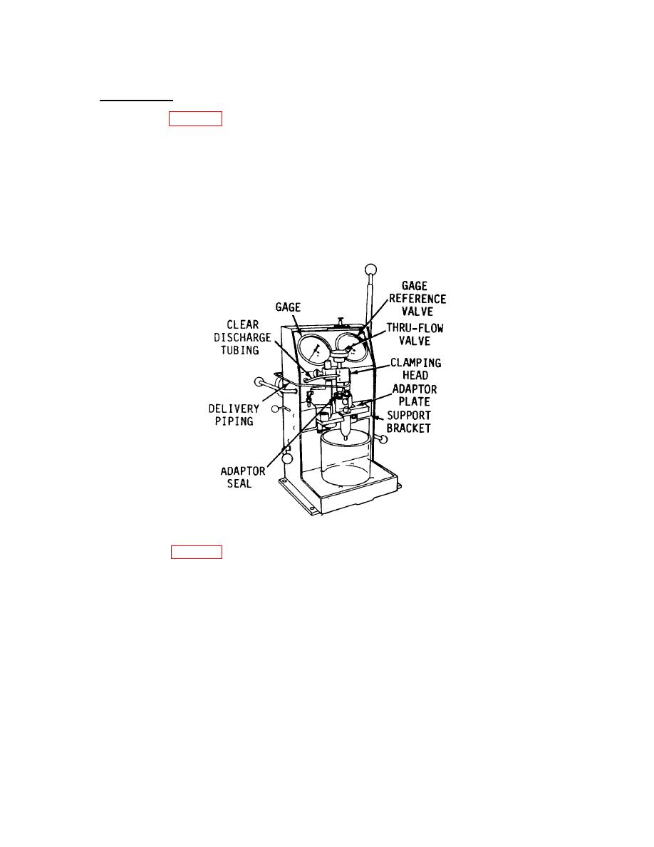
Figure 3-53. Injector Installed in Tester J23010. |
|
||
| ||||||||||
|
|
 TM 55-1930-208-24
3-22. INJECTOR, FUEL - Continued.
b. Test Continued.
(6) Refer to figure 3-53. Install the clamping head on the clamping post and tighten the setscrew into
the lower detent position.
(7) Connect the oil delivery piping to the clamping head.
(8) Connect the discharge tubing to the pipe on the clamping head.
(9) Install the injector to the adapter plate.
(10) Swing the mounted injector and adapter plate rearward and adapter plate rearward until they
contact the support bracket stop pin.
Figure 3-53. Injector Installed in Tester J23010.
(11) Refer to figure 3-54 and position injector tester levels as follows:
(a) Lever 2 up and to the rear.
(b) Lever 3 in the rear detent.
(c) Lever 4 up (horizontal).
(d) Lever 5 up (horizontal).
(12) Aline the clamping head seals over the injector filter caps.
3-84
|
|
Privacy Statement - Press Release - Copyright Information. - Contact Us |
