 |
|||
|
|
|||
|
Page Title:
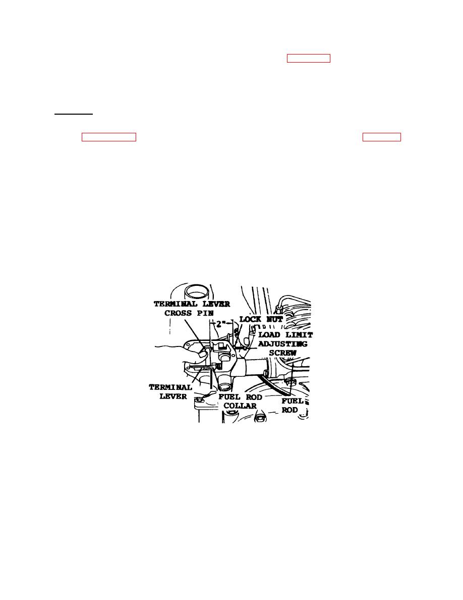
Figure 3-22. Adjusting Load Limit |
|
||
| ||||||||||
|
|
 TM 55-1930-208-24
(8) Pour approximately one pint of engine lubricating oil (item 8, Appendix C) in the top of the governor to
provide initial governor lubrication.
(9) Affix a new gasket (4) to the top of the governor sub-cap. Place governor cover (3) on top of the gasket
and install cover screws (2). Tighten the screws securely.
h.
Adjustment.
NOTE
Refer to paragraph 3-34 and adjust injector rack before adjusting the governor. (1) Refer to figure 3-22 and
loosen the load limit adjusting screw locknut and adjust the screw to obtain a distance of approximately 2
inches from the outside face of the boss on the governor sub-cap to the end of the screw.
(2) Place the fuel rod and terminal lever in the full-fuel position.
(3) Turn the load limit screw until a .020 inch space exists between the fuel rod collar and the terminal lever,
then hold the screw and tighten the locknut.
(4) Start the engine and operate at approximately one-half the rated no-load speed until the lubricating oil has
had an opportunity to warm up.
NOTE
When the engine lubricating oil is cold, the governor regulation may be erratic. The regulation should
become increasingly stable as the temperature of the lubricating oil increases. (5) Stop the engine and
remove the governor cover.
Figure 3-22. Adjusting Load Limit
3-53
|
|
Privacy Statement - Press Release - Copyright Information. - Contact Us |
