 |
|||
|
|
|||
|
Page Title:
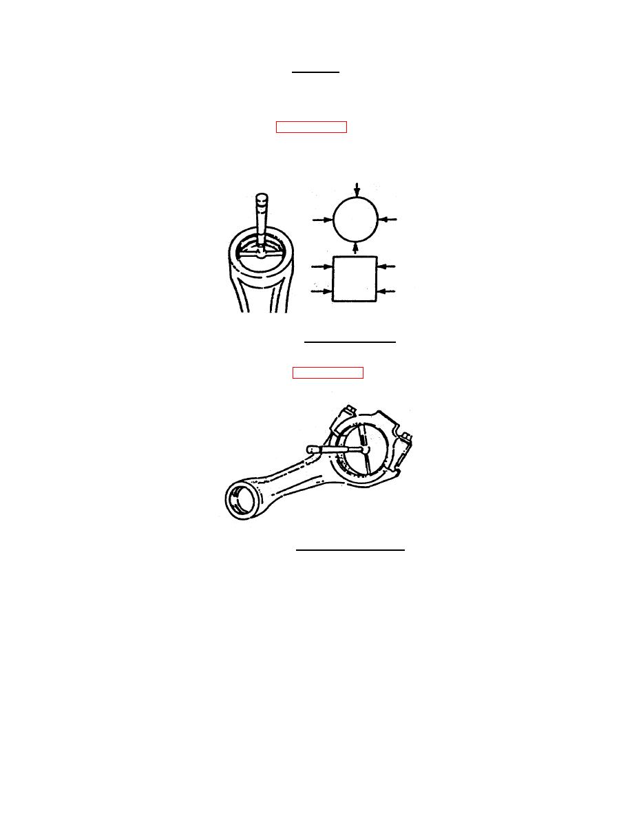
FIGURE 4-40. Measuring Pin Bore. |
|
||
| ||||||||||
|
|
 TM 55-1905-223-24-4
CAUTION
The I-Beam section cannot have dents or other damage. Damage to this part
can cause stress risers which will progress to breakage.
g.
Measure pin bore in each rod as shown in FIGURE 4-40.
Diameter: minimum 1.5769 inch (40.053 mm)
maximum 1.5784 inch (40.092 mm)
FIGURE 4-40. Measuring Pin Bore.
h.
Determine rod bearing clearance as shown in FIGURE 4-41.
FIGURE 4-41. Rod Bearing Clearance.
(1) Measure and record the crankshaft bore with the bearings (5, Figure 4-33) installed and the
capscrews (4) tightened to 73 ft-lbs (99 N-m).
4-34
|
|
Privacy Statement - Press Release - Copyright Information. - Contact Us |
