 |
|||
|
|
|||
|
Page Title:
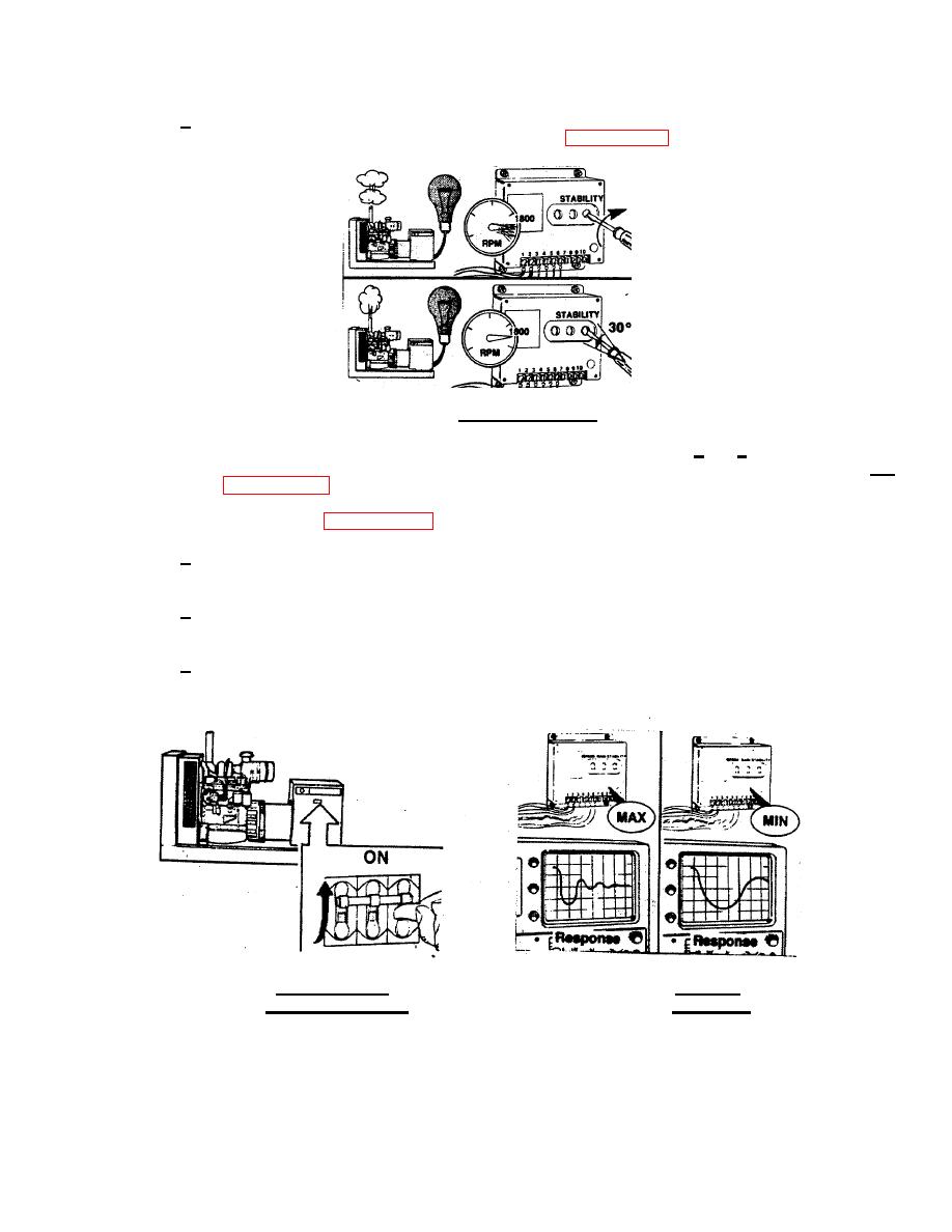
FIGURE 3-21. Stability Adjustment. |
|
||
| ||||||||||
|
|
 TM 55-1905-223-24-4
2
Slowly rotate the STABILITY adjustment clockwise until surging returns. Rotate the screw
counterclockwise 30 degrees to regain stability. (FIGURE 3-21)
FIGURE 3-21. Stability Adjustment.
(b) Load may now be applied to the generator set. If necessary, repeat steps1 and 2 until optimum
performance is obtained. Normally, the critical condition for CAIN and STABILITY adjustment is at NO
load. (FIGURE 3-22)
(c)
Optimum adjustment.(FIGURE 3-23)
1
The optimum adjustment of both controls is in the maximum clockwise position where the best
response and stability are obtained under all operating conditions.
2
Backing off slightly from this position well allow for changing conditions that may affect the
dynamic response of the engine.
3
If a load bank and recorder are available, refer to the Troubleshooting Procedures in Chapter 2,
Section III of this manual.
FIGURE 3-22. Applying a Load
FIGURE 3-23. Optimum
to the Generator Set.
Adjustment.
3-26
|
|
Privacy Statement - Press Release - Copyright Information. - Contact Us |
