 |
|||
|
|
|||
|
Page Title:
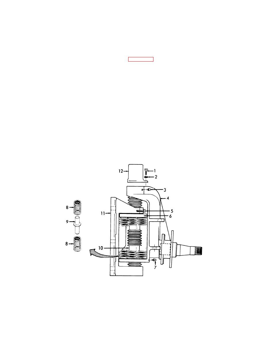
Figure 3-27. Springs, Installation |
|
||
| ||||||||||
|
|
 TM 55-1740-203-13&P
3-20. LEFT AND RIGHT SHOCK ABSORBING SPRING
A S S E M B L I E S - Continued.
Reassemble-Continued.
f.
(8) Refer to and push kingpin (10, Figure 3-27) up through top hole in knuckle (4).
(9) Aline hole in kingpin (10) with small hole in bracket (11). In-
stall cap screw (5) through bracket and into kingpin.
(10) Position six springs (8) on three spring guides (9).
(11) Place springs (8) and spring guides (9) in position on spring
support assembly (6).
(12) Using hand or screwdriver pressure, place spring (8) and
spring guide (9) assemblies into position on knuckle (4).
(13) Install cap (12), three lockwashers (2), and three bolts (1).
(14) Install two grease fittings (3 and 7).
Figure
3-27.
Springs,
Installation.
GO TO NEXT PAGE
3-59
|
|
Privacy Statement - Press Release - Copyright Information. - Contact Us |
