 |
|||
|
|
|||
|
Page Title:
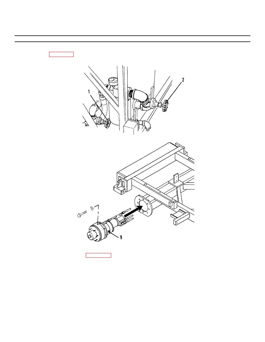
Figure 3-29.2. Hydraulic System Gate Valves. |
|
||
| ||||||||||
|
|
 TM 55-1730-228-13&P
3-28. HYDRAULIC MOTOR, BRAKE AND DRIVE HUB ASSEMBLY- REPLACE (Continued)
3-28
(9) Open (turn fully counterclockwise) the supply and return line gate valves
(1 and 2, Figure 3-29.2).
Figure 3-29.2. Hydraulic System Gate Valves.
Figure 3-29.3. Hydraulic Motor, Brake and Drive Hub, Replacement.
(10) Loosen the bleeder valve (9, Figure 3-29.3).
(11) Start the SPEMS and flick the drive mode switch until fluid is seen at
the bleeder valve. Tighten the bleeder valve.
(12) Start the SPEMS and check for proper operation and leakage. Tighten
fittings if necessary.
END OF TASK
3-70
|
|
Privacy Statement - Press Release - Copyright Information. - Contact Us |
