 |
|||
|
|
|||
|
Page Title:
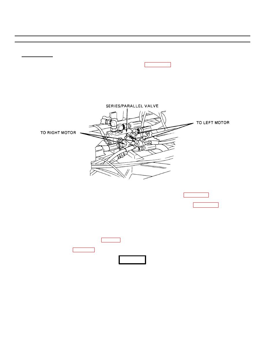
Figure 3-29.1. Series/Parallel Valve Connections. |
|
||
| ||||||||||
|
|
 TM 55-1730-228-13&P
3-28. HYDRAULIC MOTOR, BRAKE AND DRIVE HUB ASSEMBLY- REPLACE (Continued)
3-28
b. INSTALLATION:
(1) Using the identification tags, position adapter block (11, Figure 3-29), preformed packing (16), washer (15),
preformed packing (14), spacers (13) and hoses (12) on drive motor. Using two banjo fittings (10), attach block
to motor and tighten.
(2) Suspend the hub assembly (3) at the frame. Remove bleeder valve (9) from brake valve housing. Slide the hub
assembly into the frame.
Figure 3-29.1. Series/Parallel Valve Connections.
(3) Using the tags for identification, attach hydraulic hoses to series/parallel valve (Figure 3-29.1) using 2 wrenches.
(4) Turn the drive hub/brake/motor assembly as needed and install bleeder valve (9, Figure 3-29) and elbow (6).
Attach hydraulic brake hose (4) and fitting (5) to elbow (6).
(5) Attach motor case drain hose (7) to elbow (8) and tighten.
(6) Secure the assembly to the flange with eight capscrews (1) and washers (2).
(7) Install tire/wheel assembly. Refer to para 2-6.
(8) Service hub. Refer to para 3-27.
CAUTION
Gate valves must be opened prior to startup to prevent pump damage.
GO ON TO NEXT PAGE
3-69
|
|
Privacy Statement - Press Release - Copyright Information. - Contact Us |
