 |
|||
|
|
|||
|
Page Title:
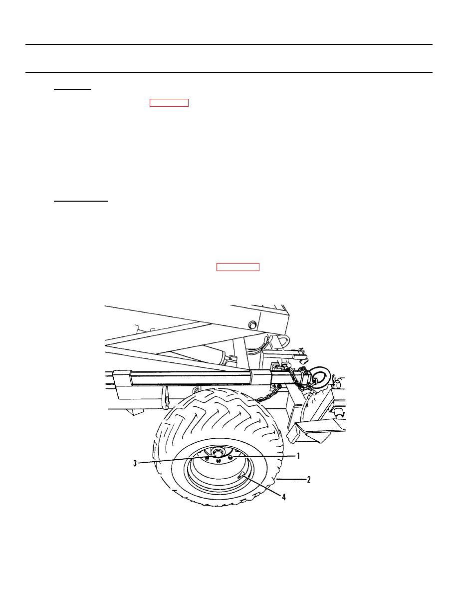
Figure 2-9. Tire/Wheel Assembly. |
|
||
| ||||||||||
|
|
 TM 55-1730-228-13&P
2-6. TIRE/WHEEL ASSEMBLIES-REPLACE (Continued)
a. REMOVAL:
(1) Loosen nine lugnuts (1, Figure 2-9) on tire/wheel assembly (2) one turn each.
(2) Raise SPEMS with floor jack until tire just comes off floor. Support SPEMS frame with jack stands and
remove floor jack.
(3) Remove nine lugnuts (1).
4) Remove tire/wheel assembly (2).
(5) Evacuate tire/wheel assembly (2) to Direct Support Maintenance for repair.
b. INSTALLATION:
(1) Place tire/wheel assembly (2) in position on hub (3) with the valve stem (4) facing out.
(2) Install nine lugnuts (1) and hand tighten.
(3) Raise SPEMS with floor jack, remove jack stands and lower SPEMS to ground.
(4) Tighten nine lugnuts (1) securely. Refer to Appendix F, Torque Limits.
END OF TASK
Figure 2-9. Tire/Wheel Assembly.
2-11
|
|
Privacy Statement - Press Release - Copyright Information. - Contact Us |
