 |
|||
|
|
|||
|
|
|||
| ||||||||||
|
|
 TM 9-6920-737-10
CREW STATION (Continued)
The following Crew Station equipment is simulated:
a.
Utility and dome lights
b.
HATCH INTERLOCK OVERRIDE, RADIO/INTERCOM, FAN DEFOGGER, and intercom floor switches.
c.
Turret position indicators, gun elevation indicator and pointer, azimuth indicator and pointer, and slope indicators.
d.
Turret travel lock, turret traverse drive select lever, TOW elevation drive select lever, gun elevation drive select
lever, turret traverse handwheel and trigger, gun elevation handwheel, coax access doors, 7.62mm machinegun
and mount, day and night sight cover handles, and browpad recoil.
e.
ISU, ISUW, CR, CFP, and auxiliary sights.
f.
Gunner's and commander's hand-stations, intercom control boxes, turret control box, weapon control box, TOW
control box, and Annunciator box.
The positions of switches and controls are monitored by the GPC. The GPC senses any change in controls which will
affect the visual scene and sends this information to the SPC. The SPC responds by changing the visual scene
accordingly; such as reticle lay, own weapon fire, and turret traverse. The GPC also determines when the crew station
equipment requires an input and simulates this input by initiating browpad recoil, panel lights and indicator readouts. The
GPC can also block responses to the Crew Station actions to simulate malfunctions.
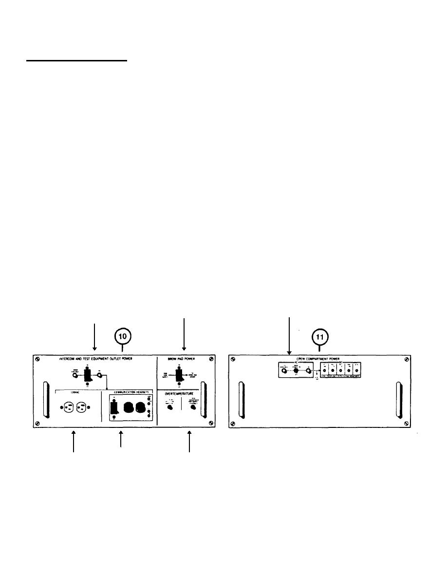
Utility Panel (10) and Power Panel (II) are on the front of the Crew Station. These panels are primarily for the use of
maintenance personnel. However, the Crew Station will not function unless the switch and circuit breakers are on. The
Instructor/Operator should be aware of these controls. In addition, overtemperature indicators are on Utility Panel (10).
These indicators allow the Instructor/Operator to pinpoint the location of an overheated unit in the Crew Station.
INTERCOM AND TEST
BROW PAD POWER
CREW COMPARTMENT POWER
EQUIPMENT OUTLET POWER
120VAC
COMMUNICATION
OVERTEMPERATURE
1-28
|
|
Privacy Statement - Press Release - Copyright Information. - Contact Us |