 |
|||
|
|
|||
|
Page Title:
INTERPRETATION OF M3 BORESCOPE VIEWS. |
|
||
| ||||||||||
|
|
 ARMY
TM 9-6650-235-13&P
MARINE CORPS
TM-08552A-13&P
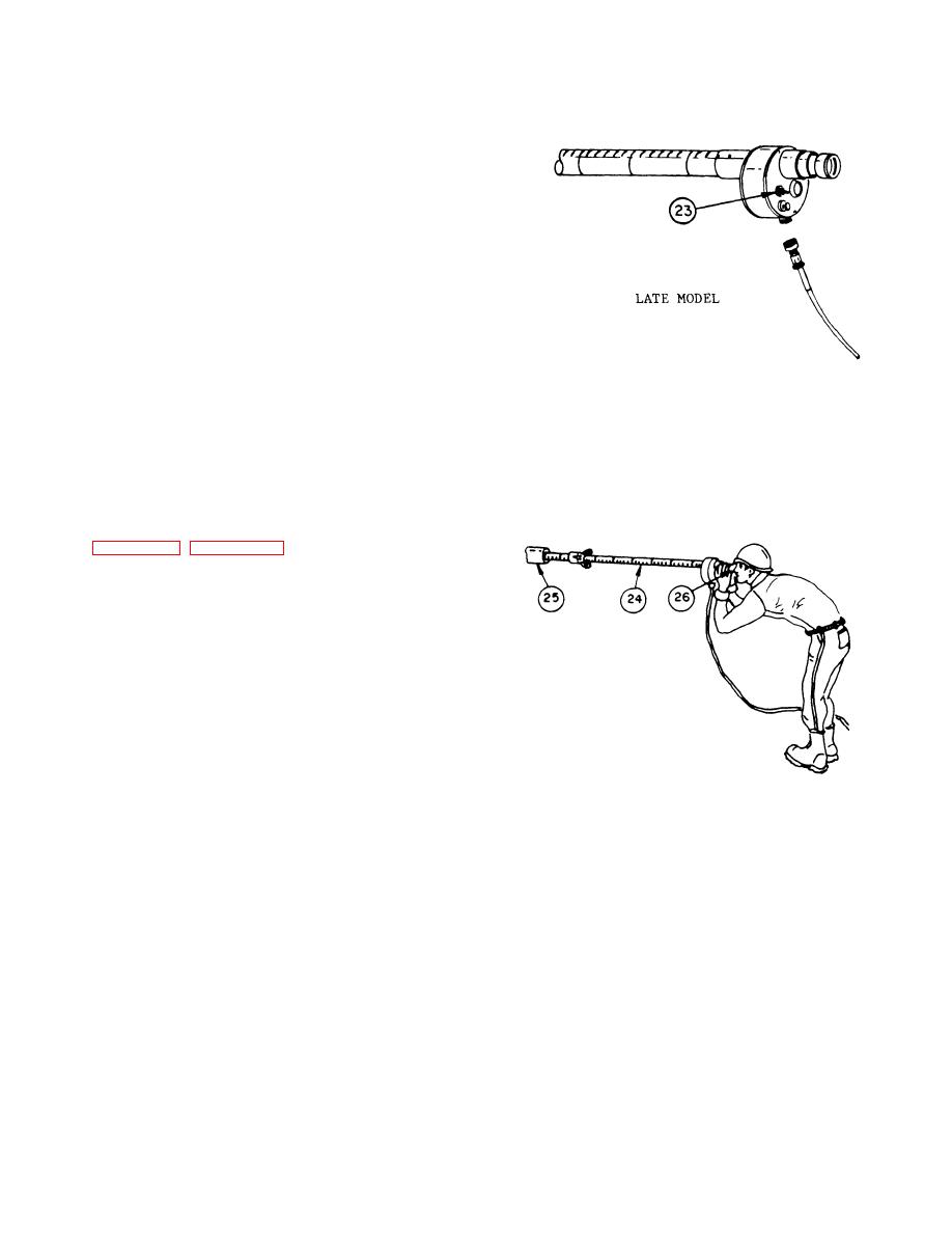
k. On later configurations, install the 115-V
electrical power cable assembly and place the 115-V/24-
V toggle switch (23) in the 115-V or 24-V position as
required.
l. The 24-V slave cord assembly or the 24-V
battery cord assembly may be used to obtain 24 volts
from vehicle for inspecting bore of weapon.
m. Insert the M3 Borescope (24) into cannon bore
(25). Adjust eyepiece assembly (26) until a clear focus is
achieved and lock in place. As the bore is examined,
turn the M3 Borescope clockwise or counterclockwise to
get complete coverage. After a complete revolution of
the M3 Borescope, move it about 1 inch (or more as
desired) and repeat the examination.
2-7. INTERPRETATION OF M3 BORESCOPE VIEWS.
The bore of the weapon as seen through the M3
Borescope is usually not life-size. Due to the various size
bores to be inspected and the design of the M3
Borescope, the magnification of the viewed area varies.
See table 2-2, page 2-16 to approximate the
magnification to be encountered in each weapon.
2-8.
RECORDING RESULTS OF M3 BORESCOPE
INSPECTION.
NOTE
The reference line that runs within 4.0
inches of the length of the extension
tubes
is always alined with the
mirror of the illuminating head
assembly.
The M3 Borescope inspection should be conducted
according to the guidance given in TM 9-1000-202-14,
Evaluation of Cannon Tubes. Results of the inspection
should be recorded by expressing the deficiency in
o'clock position and distance from the end of the cannon
tube, using the scale and reference line on the side of
the M3 Borescope.
2-15
|
|
Privacy Statement - Press Release - Copyright Information. - Contact Us |