 |
|||
|
|
|||
|
Page Title:
OPERATING INSTRUCTIONS |
|
||
| ||||||||||
|
|
 TM 9-6625-2803-14&P
6.0
OPERATING INSTRUCTIONS
6.1
TEST SET - This instrument measures complete line and
load conditions of a single and polyphase system.
Indications
will be correct for any current unbalance, provided the poly-
phase voltages are balanced.
6.2
ROTATION - Phase rotation A-B-C is assumed and must be
correct for proper indication.
If phase rotation is reversed,
the Var Meter will indicate up scale when the switch is set to
lead and the load has a lagging power factor such as an unloaded
induction motor. To correct the phase rotation, it is necessary
to interchange any two leads of a polyphase system.
6.3
PRECAUTIONS
6.3.1 NEVER connect this Test Set to a direct
current source.
6.3.2
Always set switches to Off (see below),
before applying power.
6.3.3 Always connect load leads to the same current
range on all three phases of the Test Set and to
a high enough range such that the full scale
value of the Ammeter will not be exceeded.
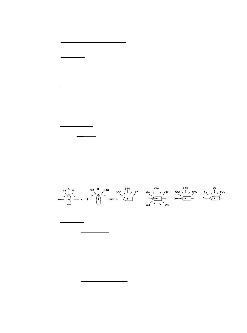
6.4
SWITCHES
6.4.1
VOLTMETER - The Voltmeter is supplied with two
switches, one for connecting the meter across the
various lines, and the second for range selection.
6.4.2
WATT/VAR METER - The Watt/Var Meter is supplied
with two switches,one for selecting single phase
watts, three phase watts or Vars, and the second
for voltage range. This switch must be set to
the same line to line voltage as the Voltmeter.
6.4.3
FREQUENCY METER - The Frequency Meter is provided
with a switch for selecting a frequency range of
45-55, 55-65 and 375-425Hz. The correct voltage
to operate the Frequency Meter is provided by
the Voltmeter circuit, when the Voltmeter reads
above mid scale.
7
|
|
Privacy Statement - Press Release - Copyright Information. - Contact Us |