 |
|||
|
|
|||
|
|
|||
| ||||||||||
|
|
 TM 9-4931-381-14&P-1
FAULT SYMPTOM INDEX
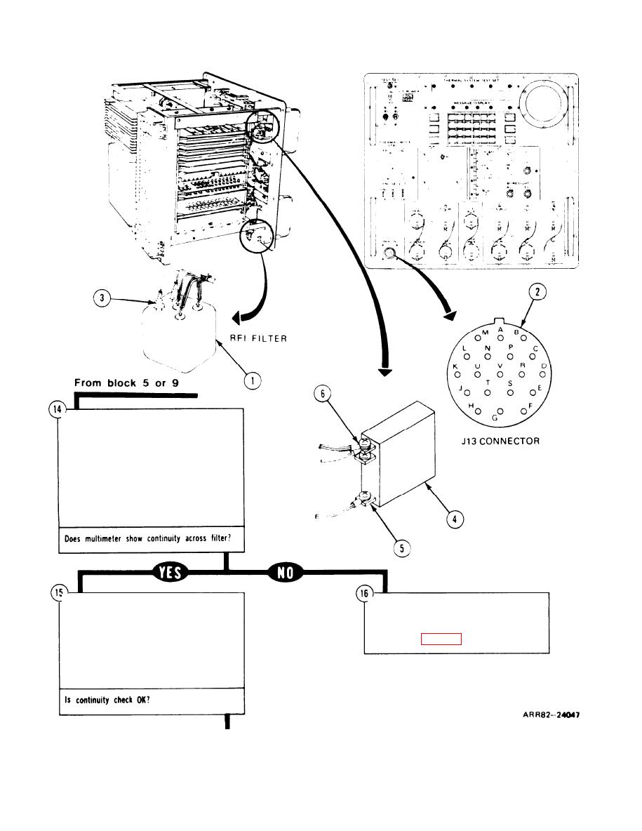
q Remove thermal system test controller.
q Refer to volume IV, para. 2-5.
q Remove RFI filter assembly (1) for access
only.
q Refer to volume IV, para. 2-6, task 14.
q Check continuity through RFI filter.
q Using multimeter, check continuity from
front panel connector J13 (2) H to RFI
filter (1) FL3 (3).
q Install RFI filter assembly (1).
q Replace RFI filter (1).
q Refer to volume IV, para. 2-6, task 14,
q Refer to volume IV, para. 2-6, task 14.
q Check continuity through circuit breaker
q Perform operator assisted self test.
q Refer to figure 6-2.
CB2.
q Using multimeter, check for continuity from
circuity breaker CB2 (4) lower lug (5) to
upper lug (6).
Figure 4-2. (Sheet 6 of 7)
Volume Ill
4-10
Para. 4-4
|
|
Privacy Statement - Press Release - Copyright Information. - Contact Us |