 |
|||
|
|
|||
|
|
|||
| ||||||||||
|
|
 TM 9- 2920- 224- 34&P
-
-
-
ASSEMBLY OF THE GENERATOR - CONTINUED
-
0010 00
Assembly
1. Electrical End Bell.
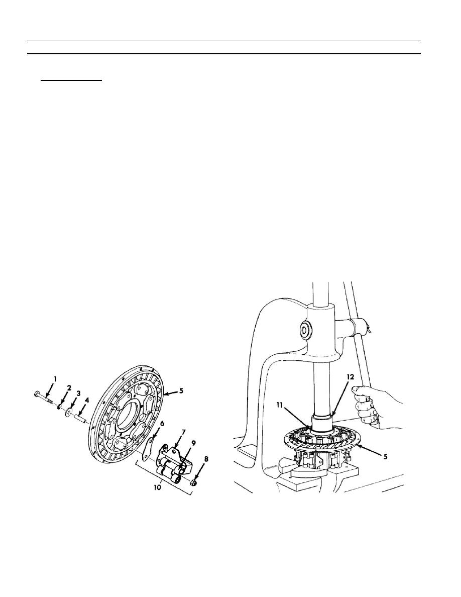
a. Install metal flat washer (2), insulating flat washer (3), and tube (4) on each of two machine bolts (1). Install
these bolts through one brush holder pad on generator support assembly (5).
b. Install one plate insulator (6) over ends of bolts (1), make sure contour of insulator (6) fits contour of brush
holder pad on support assembly (5).
c.
Position one holder (7) over ends of bolts (1) and against plate insulator (6) on support assembly (5). Install
and tighten two new self--locking nuts (8). Torque to 25--30 Ib--in (2.8 to 3.4 Nm).
d. Install each of remaining five electrical contact assemblies (10) by repeating steps a thru c. If torsion spiral
springs (9) were removed for inspection or replacement during disassembly, install all springs (9) on their
respective holders (7) in the position shown.
e. Apply a coating of insulating compound to the head of each bolt (1), make sure that compound covers both
flat washers (2) and (3). Apply compound around attaching flange of each holder (7) and mounting pad on
support assembly (5). Allow compound to dry thoroughly before installing bearing in support assembly.
f.
Apply a film of light grease to bore of bearing liner in support assembly (5) and press annular ball bearing (11)
into bore of support assembly (5) as shown. Use an arbor press and an arbor (12) slightly smaller in diameter
than outside diameter of outer bearing race, as it must make contact with outer bearing race only.
g. Check insulation of electrical end bell. Using a multimeter, check continuity on each brush holder terminal.
Multimeter should read 0 continuity between brush holder.
0010 00- 2
-
|
|
Privacy Statement - Press Release - Copyright Information. - Contact Us |