 |
|||
|
|
|||
|
Page Title:
Repair of Fuel Density Compensator Assemblies |
|
||
| ||||||||||
|
|
 TM 9-2910-226-34
density compensator assemblies. Do not
disassemble.
a. Discard original type (2910-017-9776) and retain
other types (2910-907-0665 or 2910-125-3793) for
possible reuse.
b. New compensator assemblies are furnished
calibrated and do not have to be checked for
calibration before installation. If it should be
necessary to check operation of a new or used
compensator, it may be functionally inspected in the
following steps.
(1) Manually operate stop plate (fig. 3-51)
through full travel. It must have smooth action with
no indication of sticking.
(2) Apply 35-45 psi fuel pressure to compensator
fuel inlet (fig. 3-51); and stop plate must move to the ,
up position.
(3) Manually depress stop plate to full travel.
Note that remaining travel, when pressurized is
0.040 to 0.060-inch. This will cover a fuel range of -
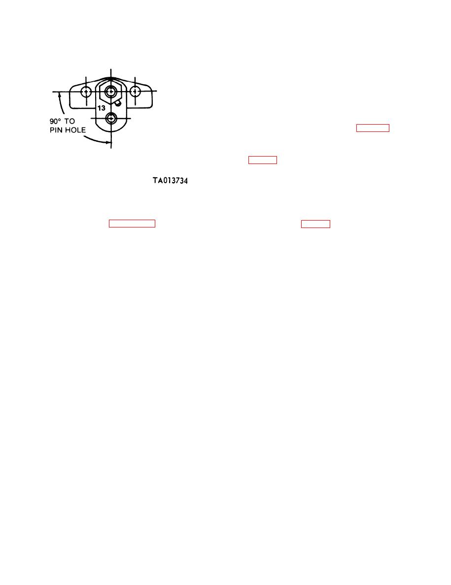
Figure 3-50. Fuel control lever identification (code G pump).
DF-1 and DF-2. If travel is more than 0.060-inch,
(3) Final inspection of the fuel control unit will
replace the compensator.
be accomplished at fuel injection pump calibration
(4) Plug fuel inlet and apply 10 psi fuel pressure
to fuel outlet connection (fig. 3-51) and maintain for
plunger sleeve pin (A). Install new control unit
approximately one minute.
packing (B).
3-24. Repair of Fuel Density Compensator
Assemblies.
NOTE
There are no service or spare parts for fuel
3-36
|
|
Privacy Statement - Press Release - Copyright Information. - Contact Us |
