 |
|||
|
|
|||
|
|
|||
| ||||||||||
|
|
 TM 9-2815-224-34&P
Engine Brake Retarder Maintenance Instructions (Cont)
11-2.
ENGINE BRAKE RETARDER REMOVAL/INSTALLATION (CONT).
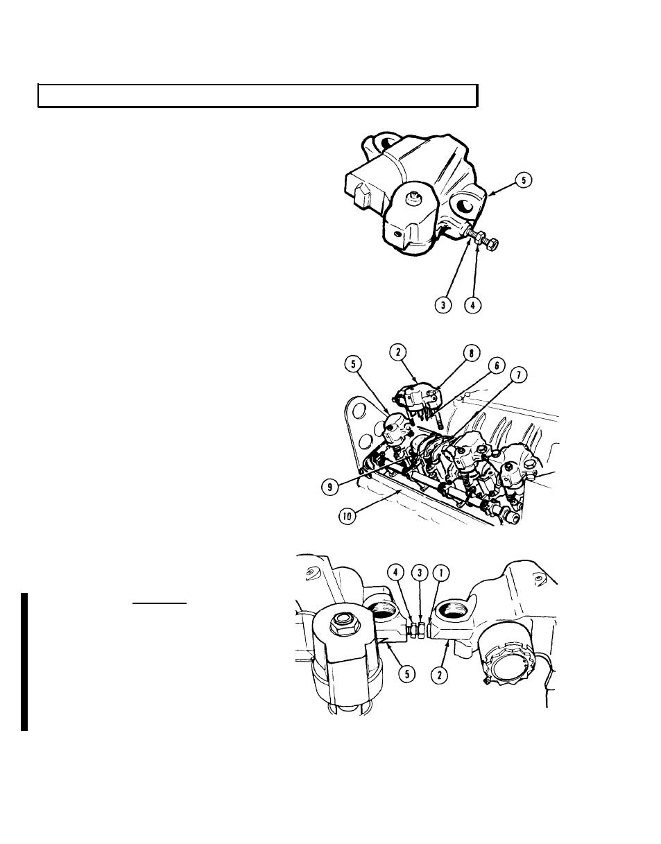
Install connector (3) with nut (4) in drone (5).
(2)
Screw connector (3) in about 1/2-in. (13 mm).
(3)
NOTE
Clean engine mounting surface before
positioning supply brakes and drones on
engine.
Position master piston fork assembly (6)
(4)
over injector rocker clevis (7).
Install supply brake (2) and drone (5)
(5)
with four mounting screws (8) through
rocker arm shaft (9) to cylinder
head (10).
Tighten screws (8) to 45 lb-ft (61 Nm).
(6)
Tighten screws (8) to 88 to 92 lb-ft (119
(7)
to 124 Nm).
Move master piston fork assembly (6) up
(8)
and down several times to make sure it
rides freely on injector rocker clevis (7).
Unscrew connector (3) from drone (5)
(9)
until connector covers seal ring (1) and
makes contact with supply brake (2).
CAUTION
Be sure screw is backed out 1/3 turn from
contact point to provide working clearance. If
the screw is allowed to contact adjacent
housing during brake operation, the screw will
break resulting in leakage and loss of engine
braking.
After connector (3) makes contact, back
(10)
off connector 1/3 turn. Hold connector
and tighten nut (4) against drone (5).
11-4
Change 2
|
|
Privacy Statement - Press Release - Copyright Information. - Contact Us |